Table of Contents
Advertisement
A421 Series Electronic Temperature Controls with
Off-Cycle Defrost
Installation Instructions
A421ABD-x, A421AED-x
Applications
IMPORTANT: Use this A421 Series Electronic
Temperature Control only as an operating control.
Where failure or malfunction of the A421 control could
lead to personal injury or property damage to the
controlled equipment or other property, additional
precautions must be designed into the control
system. Incorporate and maintain other devices, such
as supervisory or alarm systems or safety or limit
controls, intended to warn of or protect against failure
or malfunction of the A421 control.
IMPORTANT: Utiliser ce A421 Series Electronic
Temperature Control uniquement en tant que
dispositif de régulation. Lorsqu'une défaillance ou un
dysfonctionnement du A421 control risque de
provoquer des blessures ou d'endommager
l'équipement contrôlé ou un autre équipement, la
conception du système de contrôle doit intégrer des
dispositifs de protection supplémentaires. Veiller
dans ce cas à intégrer de façon permanente
d'autres dispositifs, tels que des systèmes de
supervision ou d'alarme, ou des dispositifs de
sécurité ou de limitation, ayant une fonction
d'avertissement ou de protection en cas de
défaillance ou de dysfonctionnement du
A421 control.
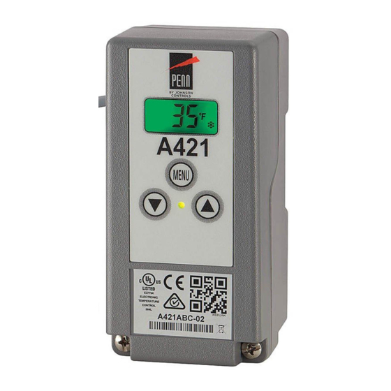
The A421 Series Electronic Temperature Controls are
single-stage, electronic temperature controls with a
single-pole, double-throw (SPDT) output relay.
A421 controls feature a backlit LCD with adjustable
brightness and three-button touchpad interface that
can be set up to restrict user adjustments. An LED
indicates the output relay's On/Off status.
A421 controls have simple On and Off temperature
settings for heating or cooling, an adjustable anti-short
cycle delay, temperature setback, and sensor offset
capability. The temperature control range is
40 to 212°F or -40 to 100°C.
The A421 controls are available either in Type 1
(NEMA), IP20 (CE), high-impact plastic enclosures
suitable for surface or DIN rail mounting (Figure 1)
or in Type 4X (NEMA), IP66 (CE) watertight, corrosion
resistant surface mount enclosures (Figure 2).
A421 Series Electronic Temperature Controls with Off-Cycle Defrost Installation Instructions
Refer to the
QuickLIT website
Dimensions
Figure 1: A421 Control with Type 1 (NEMA),
IP20 Enclosure Dimensions, in. (mm)
Figure 2: A421 Control with Type 4X (NEMA),
IP66 Enclosure Dimensions, in. (mm)
1
Part No. 24-7664-3035, Rev. A
Issued November 25, 2015
for the most up-to-date version of this document.
Advertisement
Table of Contents

Related Manuals for Penn A421ABD Series


Summary of Contents for Penn A421ABD Series
- Page 1 A421 Series Electronic Temperature Controls with Off-Cycle Defrost Installation Instructions Part No. 24-7664-3035, Rev. A Issued November 25, 2015 A421ABD-x, A421AED-x Refer to the QuickLIT website for the most up-to-date version of this document. Applications Dimensions IMPORTANT: Use this A421 Series Electronic Temperature Control only as an operating control.
- Page 2 Each A421 Control includes a Johnson Controls/ • Ensure that the mounting surface can support the PENN® A99 Series temperature sensor. See A99 control, DIN rail, mounting hardware, and any Series Temperature Sensors, Wiring, and Technical (user-supplied) panel or enclosure.
- Page 3 To direct-mount a Type 1/IP20 control to a wall or Wiring other flat surface using the four keyhole slots: Observe the following guidelines. 1. Remove the enclosure cover, place the control WARNING: Risk of Electric Shock. horizontally against the wall surface in a suitable Disconnect or isolate all power supplies location, and mark the keyhole slot locations on the before making electrical connections.
- Page 4 Table 1: Maximum Recommended Sensor Cable IMPORTANT: When connecting an A99 sensor Lengths and Wire Sizes with a shielded cable to an A421 Control, connect Wire the cable shield drain lead to the COM (common) Maximum Sensor Cable Length Gauge terminal on the sensor and binary input terminal Feet (Meters) block (TB3).
- Page 5 Figure 4: Wiring the A421 Series Controls Using the Same Power Source to Power the Control Operation and Power the Controlled Equipment Table 2: A421 Control Wiring Terminals and Wire Size Information (Part 1 of 2) Terminal Label Description, Function, and Requirements Recommended Block Wire Sizes...
-
Page 6: Setup And Adjustments
Table 2: A421 Control Wiring Terminals and Wire Size Information (Part 2 of 2) Terminal Label Description, Function, and Requirements Recommended Block Wire Sizes Detects a switch closure between the BIN and COM terminals and 22 AWG (0.34 mm manually starts or stops a defrost cycle. (This is now the default behavior stranded, shielded for the binary input.) cable recommended... - Page 7 The heating or cooling mode is determined by the On Temperature Units (Un): Select the desired and OFF value relationship as follows: temperature scale for your application. Select either the Fahrenheit (°F) or Celsius (°C) temperature scale. • OFF > On = Heating mode = Flame icon Note: After changing the temperature units value •...
- Page 8 Sensor Offset Adjustment (So): Sensor offset allows Defrost Interval (dI): Select the time (in hours) you to compensate for any difference between the between the start of a defrost cycle and the next displayed temperature value and the temperature defrost cycle. The dI value can be set to 0 or 2 to 24 sensed at the A99 sensor.
-
Page 9: A421 Control Parameter Setup Menus
Table 3: Standard Parameter Setup Codes, Descriptions, Range of Values, and Default Values Parameter Parameter Description (Menu) Range of Usable Values Factory Default Code Value Start or Stop Defrost Off-Cycle (Advanced Change 0 to 1 to Start a new only) Defrost Cycle Change 1 to 0 to Stop a Defrost Cycle... - Page 10 2. Press or to scroll through all of the Basic parameter codes and display the preferred code. 3. With the preferred parameter code displayed, press MENU to display the current parameter value for the code. 4. With the current parameter value displayed, press ...
- Page 11 Viewing and Changing Values in the Advanced Setting Up a Defrost Off-Cycle Menu Setting Up a Regular/Timed Defrost Off-Cycle To access the Advanced menu and view and change The following behavior is enforced: the parameter values, follow these steps: • At power up, the initial Defrost Interval (dI) does 1.
- Page 12 4. Or, change the SdF value to 0 during a defrost cycle and return to normal On/Off operation. See Figure 10. Figure 10: Manual Defrost Only: Behavior When dI is Set to 0 Control Behavior When Starting or Stopping an SdF Parameter: To start or stop a Defrost Cycle using Automatically Enabled Defrost Off-Cycle the SdF parameter:...
-
Page 13: Restricting User Adjustment
Figure 11: Starting and Stopping a dFt: Behavior Using SdF Parameter and Momentary Contact Switch Restricting User Adjustment • The OFF value can only be adjusted to values that maintain the entire control band within the You can restrict user adjustment of the A421 control to restricted temperature adjustment range defined either just OFF value (control band) adjustment within by HtS and LtS. - Page 14 3. Change the HtS and LtS temperature values to Adjusting the Control In Restricted Mode define the restricted adjustment range (Figure 12). To adjust the OFF value (and shift the On/OFF control band) within the restricted adjustment range, when the 4.
-
Page 15: Fault Codes
Troubleshooting Fault Codes A421 Series controls display fault codes on the LCD as described in Table 4. Table 4: Fault Codes Defined Fault Code Definition System Status Solution SF flashing Open temperature sensor or Output functions according See Troubleshooting Procedure. Cycle alternately with sensor wiring to the selected sensor failure... -
Page 16: Repair Information
A421 controls. Contact your equipment manufacturer’s instructions for nearest Johnson Controls/PENN distributor or sales troubleshooting the controlled equipment. representative to order these products. Table 5: A421 Series Electronic Temperature Controls with Off-Cycle Defrost Timer Selection Chart... -
Page 17: Technical Specifications
Table 6: A99 Temperature Sensors Selection Chart (Part 2 of 2) Product Code Description PTC Temperature Sensor: Standard probe 2 in. (5.1 cm) with 3.3 ft (1.0 m) high-temperature silicon A99BC-100C cable; Ambient operating temperature range: -40 to 248ºF (-40 to 120ºC) PTC Temperature Sensor: Standard probe 2 in. - Page 18 Table 9: A421 Temperature Control Output Relay Contacts Electrical Ratings Agency and File UL 60730 and EN 60730 Applied AC Voltage at 50/60 Hz 120 VAC 208 VAC 240 VAC Horsepower LC/LNO (LC/LNC) 1 (0.25) 1 (0.3) 1 (0.5) Full Load Amperes LC/LNO (LC/LNC) 16 (5.8) 9.2 (4) 8 (4.9)
- Page 19 Building Efficiency 507 E. Michigan Street, Milwaukee, WI 53202 Johnson Controls® and PENN® are registered trademarks of Johnson Controls, Inc. in the United States of America and/or other countries. All other trademarks used herein are the property of their respective owners. © Copyright 2015 by Johnson Controls, Inc. All rights reserved.
Need help?
Do you have a question about the A421ABD Series and is the answer not in the manual?
Questions and answers