Table of Contents
Advertisement
Introduction . . . . . . . . . . . . . . . . . . . . . . . . . . . . . . . . . . . . . . . . . . . . . . . . . . . . . . . . . . . . . . . . .3
Application . . . . . . . . . . . . . . . . . . . . . . . . . . . . . . . . . . . . . . . . . . . . . . . . . . . . . . . . . . . . . . . . .3
A5xx Series Wall Mount Refrigeration and Defrost Controllers . . . . . . . . . . . . . . . . . . . . . . . . .3
A5xx Controller UI . . . . . . . . . . . . . . . . . . . . . . . . . . . . . . . . . . . . . . . . . . . . . . . . . . . . . . . . . . .4
Cleaning the controller . . . . . . . . . . . . . . . . . . . . . . . . . . . . . . . . . . . . . . . . . . . . . . . . . . . . . .6
Terminal block and terminal descriptions . . . . . . . . . . . . . . . . . . . . . . . . . . . . . . . . . . . . . . . .6
Refrigeration mode . . . . . . . . . . . . . . . . . . . . . . . . . . . . . . . . . . . . . . . . . . . . . . . . . . . . . . . .9
Defrost mode . . . . . . . . . . . . . . . . . . . . . . . . . . . . . . . . . . . . . . . . . . . . . . . . . . . . . . . . . . . .10
Defrost types . . . . . . . . . . . . . . . . . . . . . . . . . . . . . . . . . . . . . . . . . . . . . . . . . . . . . . . . . . . .11
Defrost termination types . . . . . . . . . . . . . . . . . . . . . . . . . . . . . . . . . . . . . . . . . . . . . . . . . . .11
Defrost schedule types . . . . . . . . . . . . . . . . . . . . . . . . . . . . . . . . . . . . . . . . . . . . . . . . . . . .12
Compressor and evaporator fan start delays . . . . . . . . . . . . . . . . . . . . . . . . . . . . . . . . . . . .12
System setup parameters . . . . . . . . . . . . . . . . . . . . . . . . . . . . . . . . . . . . . . . . . . . . . . . . . .14
Adaptive defrost setup parameters . . . . . . . . . . . . . . . . . . . . . . . . . . . . . . . . . . . . . . . . . . .18
Universal inputs and alarms . . . . . . . . . . . . . . . . . . . . . . . . . . . . . . . . . . . . . . . . . . . . . . . . .19
Cooling and system shutdown . . . . . . . . . . . . . . . . . . . . . . . . . . . . . . . . . . . . . . . . . . . . . . .22
Detailed procedures . . . . . . . . . . . . . . . . . . . . . . . . . . . . . . . . . . . . . . . . . . . . . . . . . . . . . . . . .23
Setting up the A5xx Controller . . . . . . . . . . . . . . . . . . . . . . . . . . . . . . . . . . . . . . . . . . . . . . .23
Navigating the high-level status and setup start screens . . . . . . . . . . . . . . . . . . . . . . . . . . .24
Viewing the system status screens . . . . . . . . . . . . . . . . . . . . . . . . . . . . . . . . . . . . . . . . . . .25
Viewing the QREV/PSHC status screens . . . . . . . . . . . . . . . . . . . . . . . . . . . . . . . . . . . . . .26
Setting up the system setup screens . . . . . . . . . . . . . . . . . . . . . . . . . . . . . . . . . . . . . . . . . .27
Setting up the system components . . . . . . . . . . . . . . . . . . . . . . . . . . . . . . . . . . . . . . . . . . .29
Setting up the system setup parameters . . . . . . . . . . . . . . . . . . . . . . . . . . . . . . . . . . . . . . .31
Setting up the refrigeration setup screens . . . . . . . . . . . . . . . . . . . . . . . . . . . . . . . . . . . . . .32
Setting up the defrost setup screens . . . . . . . . . . . . . . . . . . . . . . . . . . . . . . . . . . . . . . . . . .33
Setting up the universal inputs . . . . . . . . . . . . . . . . . . . . . . . . . . . . . . . . . . . . . . . . . . . . . . .36
Setting up the alarm setup . . . . . . . . . . . . . . . . . . . . . . . . . . . . . . . . . . . . . . . . . . . . . . . . . .37
Using file to import and export data . . . . . . . . . . . . . . . . . . . . . . . . . . . . . . . . . . . . . . . . . . .38
A5xx Controller screens . . . . . . . . . . . . . . . . . . . . . . . . . . . . . . . . . . . . . . . . . . . . . . . . . . . . . .39
Info field codes . . . . . . . . . . . . . . . . . . . . . . . . . . . . . . . . . . . . . . . . . . . . . . . . . . . . . . . . . . . . .54
Electrical ratings . . . . . . . . . . . . . . . . . . . . . . . . . . . . . . . . . . . . . . . . . . . . . . . . . . . . . . . . . . . .56
Technical specifications . . . . . . . . . . . . . . . . . . . . . . . . . . . . . . . . . . . . . . . . . . . . . . . . . . . . . .57
North American emissions compliance . . . . . . . . . . . . . . . . . . . . . . . . . . . . . . . . . . . . . . . . . .59
United States . . . . . . . . . . . . . . . . . . . . . . . . . . . . . . . . . . . . . . . . . . . . . . . . . . . . . . . . . . . .59
Canada . . . . . . . . . . . . . . . . . . . . . . . . . . . . . . . . . . . . . . . . . . . . . . . . . . . . . . . . . . . . . . . . 59
1
LIT No. 12012405
Advertisement
Table of Contents

Related Manuals for Penn A5 Series


Summary of Contents for Penn A5 Series
-
Page 1: Table Of Contents
A5xx Series Wall Mount Refrigeration and Defrost Controllers Technical Bulletin LIT No. 12012405 Issued December 2018 A525 Introduction ..............3 Application . -
Page 3: A5Xx Series Wall Mount Refrigeration And Defrost Controllers Technical Bulletin
A5xx Series Wall Mount Refrigeration and Defrost Controllers Technical Bulletin LIT No. 12012405 Issued December 2018 A525 Refer to the QuickLIT website for the most up-to-date version of this document. Introduction This document describes the features and functions of the A5xx Series Wall Mount Refrigeration and Defrost Controller, and provides guidelines and instructions to set up, adjust, and troubleshoot the controller. -
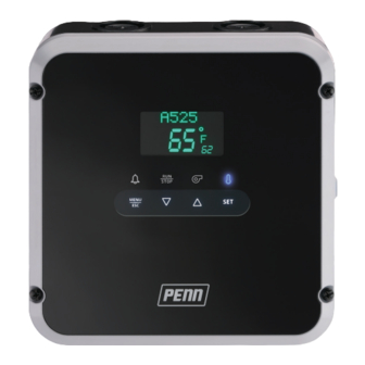
Page 4: A5Xx Controller Ui
A5xx Controller UI The A5xx Controller’s system status and setup information displays on an LCD UI with adjustable brightness. The four status indicator icons show the defrost, cooling, evaporator fan, and alarm features and provide a visual indication of the system status and alarms. The Defrost and Alarm icons also function as keys. You can use these keys to initiate unscheduled defrost cycles and clear system alarms. - Page 5 Table 1: A5xx Controller UI with display fields, icons, and touchpad keys callout table (Part 2 of 2) Callout Item Description, behavior, or user-action Degree The degree symbol displays when a temperature value displays in the status field. symbol Save icon When you press SET to save a parameter value or a menu selection, the save icon blinks to indicate that the controller saved the value or selection.
-
Page 6: Cleaning The Controller
Cleaning the controller Remove any loose debris from the controller. Use a soft cloth with a warm, mild detergent solution to wipe the exterior surface. Rinse the cloth with clean water and wipe the controller until it is clean. Dry the controller with a soft cloth. - Page 7 Low-voltage terminal blocks and terminals The following figure and table provide information about the low-voltage wiring terminal blocks and wiring terminal labels. Note: For detailed wiring guidelines and instructions, refer to the A5xx Series Wall Mount Refrigeration and Defrost Controller Installation Instructions (part no. 24-7664-3310). Figure 3: A5xx Controller low-voltage terminal block connections (internal to control) RS485 MODBUS...
- Page 8 High-voltage terminal blocks and terminals The following figure and table provide information about the high-voltage wiring terminal blocks and wiring terminal labels. Note: For detailed wiring guidelines and instructions, refer to the A5xx Series Wall Mount Refrigeration and Defrost Controller Installation Instructions (part no. 24-7664-3310). Figure 4: A5xx Controller high-voltage terminal block connections (internal to control) L2/N...
-
Page 9: Refrigeration Mode
Refrigeration mode Refrigeration mode is the normal operating mode of the A5xx Controller. The controller cycles the compressor on and off and operates the evaporator fans according to the setup selections to maintain the setpoint temperature in the refrigerated space. The controller displays the following behaviors in refrigeration mode: •... -
Page 10: Defrost Mode
Defrost mode Your selections for defrost type, defrost termination type, and evaporator fan behavior determine how the refrigeration system operates in defrost mode. For more information, see Defrost intervals and durations and Defrost termination types. To manually start or stop a defrost duration, press and hold the Defrost icon for 2 seconds. -
Page 11: Defrost Types
Defrost types The A5xx Controller provides defrost control for off-cycle defrost systems on medium temperature refrigeration applications of 2°C to 7°C or 35°F to 45°F. The controller also provides defrost control for electric heat or hot gas defrost systems on low-temperature refrigeration applications of less than 2°C or 35°F. Off-cycle defrost Off-cycle (passive) defrost does not use the defrost relay. -
Page 12: Defrost Schedule Types
Temperature switch defrost termination You can also use a line-voltage temperature defrost termination switch connected to the high-voltage binary input (HVBIN) terminals to terminate the defrost durations in the refrigeration application. The temperature termination switch is mounted on the evaporator coil and has a fixed temperature termination value. You do not need to set a defrost termination temperature value during defrost setup. - Page 13 Figure 7: ASD overriding load demand to maintain compressor relay off ASD overrides load demand Load demand Compressor relay When ASD elapses, ASD starts the existing demand when the relay closes the relay (on) Compressor opens (off) relay cycling on load demand Table 6: ASD overriding load demand callout table Item...
-
Page 14: System Setup Parameters
Figure 8: A5xx Controller relay states during defrost duration, drip-time delay, and evaporator fan delay Time Compressor relay Defrost relay Hi-spd fan relay (single-speed) Table 7: A5xx Controller relay states during defrost duration, drip-time delay, and evaporator fan delay callout table Item Description Relay off... - Page 15 QREV/PSHC setup The A5xx Controller can communicate with an optional PENN® QREV/PSHC. The QREV is a proportional control expansion valve that uses microelectromechanical system (MEMS) microvalve technology to provide precise flow control for industry standard HVAC and refrigeration applications.
- Page 16 Evaporator fan control The behavior of the evaporator fan depends on the following conditions: • Whether the evaporator fan is one-speed or two-speed • Whether the system’s mode of operation is refrigeration or defrost • The selected evaporator setup options in the refrigeration and defrost setup screens Evaporator fan operation in refrigeration mode In normal refrigeration mode, you can set a single-speed evaporator fan to run continuously or to cycle on and off with the compressor.
- Page 17 The following figure shows the compressor, lo-spd aux relay, and hi-spd relay states for a two-speed evaporator fan operating in normal refrigeration mode. The high-speed fan is on continuously. Figure 10: Compressor, lo-spd aux, and hi-spd relay states for two-speed evaporator fan in refrigeration mode Time Compressor relay...
-
Page 18: Adaptive Defrost Setup Parameters
The following figure shows the compressor, lo-spd aux relay, and hi-spd relay states for two-speed evaporator fans operating in refrigeration mode. The evaporator fan is set to low-speed when the compressor is off and high-speed when the compressor is on. Figure 11: Compressor, lo-spd aux, and hi-spd relay states for two-speed evaporator fan in refrigeration mode with low-speed and high-speed setup Time... -
Page 19: Universal Inputs And Alarms
Defrost interval The defrost interval is an estimate of the number of hours between the start of consecutive defrost cycles. You enter the expected defrost interval time in hours for the first defrost interval. The adaptive defrost feature shortens or lengthens the defrost interval to reach the defrost termination temperature in the expected defrost duration. This value provides a starting point for the adaptive defrost algorithm. - Page 20 Table 11: A5xx Controller universal input modes and controller actions Mode Action when Description condition is true None None The status of the universal input has no effect on the controller. Refrigerant leak System shutdown The system remains shut down as long as the refrigerant leak condition persists. A system shutdown takes priority over the normal control of the compressor, defrost, and fan relays.
- Page 21 Alarm setup parameters The following table provides information about the A5xx Controller’s alarms and their corresponding true conditions. Notes: • Some of the following alarms are available only when the A5xx Controller uses the corresponding binary input or feature. For example, the QREV/PSHC alarms are available only after you pair the A5xx Controller with a QREV/PSHC.
-
Page 22: Cooling And System Shutdown
Setting up the alarm setup parameters The following table provides information about the alarm parameters and their corresponding descriptions. Table 14: A5xx Controller alarm parameters and descriptions Alarm parameter Description Threshold Each alarm uses specific levels, units, or ranges for its threshold. For example, temperature alarms use Fahrenheit or Celsius values, the door open alarm uses a time value, and a binary input uses a 1 or 0 or open or closed to indicate an alarm state. -
Page 23: Detailed Procedures
Detailed procedures The following sections provides detailed information about the setup procedures for the A5xx Controller. Setting up the A5xx Controller To set up the A5xx Controller, set the physical components and features of the controller in the system setup screens. -
Page 24: Navigating The High-Level Status And Setup Start Screens
Navigating the high-level status and setup start screens To move through the high-level status and setup start screens, press the DOWN and UP arrow keys. Note: The QREV/PSHC STATUS screens are available only if you install a QREV/PSHC to the controller and set up the interface. -
Page 25: Viewing The System Status Screens
Viewing the system status screens The SYSTEM STATUS screens display the status of the sensors, the cooling system, the universal inputs, and the system control relays. These screens also identify the firmware versions on the controller. You can use the information on these screens to troubleshoot system and controller problems. -
Page 26: Viewing The Qrev/Pshc Status Screens
Viewing the QREV/PSHC status screens The A5xx Controller can monitor and control a QREV/PSHC. To view the QREV/PSHC STATUS screens, navigate to the QREV/PSHC STATUS start screen and press SET to go to the QREV/PSHC: SUPERHEAT screen. To move through the QREV/PSHC STATUS screens, press the DOWN and UP arrow keys. Note: The QREV/PSHC STATUS screens are available only if you install a QREV/PSHC to the controller and set up the interface. -
Page 27: Setting Up The System Setup Screens
Setting up the system setup screens To begin the set up procedure for the A5xx Controller, define the following settings for the refrigeration system in the system setup screens. • System date and time. For more information, see Setting up the system date and time. •... - Page 28 Setting up the system date and time To set up the date and time on the A5xx Controller, navigate to the SYSTEM SETUP start screen and press SET to go to the DATE/TIME start screen. To move through the DATE/TIME screens, press the DOWN and UP arrow keys.
-
Page 29: Setting Up The System Components
Setting up the system components To define the sensors, evaporator fan motors, defrost system type, and defrost termination type on the controller, navigate to the SYSTEM SETUP start screen and press SET. To move through the system component screens, press the DOWN and UP arrow keys. Note: The selections that you make in the following setup screens determine many of the setup screens that appear in the REFRIGERATION SETUP and DEFROST SETUP menus. - Page 30 Setting up the QREV/PSHC setup To set up the QREV/PSHC setup parameters, navigate to the SYSTEM SETUP start screen and press SET. To move through the QREV/PSHC screens, press the DOWN and UP arrow keys. Note: If you select NO in the PSHC INSTALLED screen, the QREV/PSHC SUPERHEAT and QREV/PSHC REFRIGERANT screens do not appear.
-
Page 31: Setting Up The System Setup Parameters
Setting up the system setup parameters To set up the system setup parameters, navigate to the SYSTEM SETUP start screen and press SET. To move through the system component screens, press the DOWN and UP arrow keys. SYSTEM SETUP WELCOME TO A52x In the DATE/TIME start screen, go to the SYSTEM NAME screen and press SET. -
Page 32: Setting Up The Refrigeration Setup Screens
Setting up the refrigeration setup screens To set up the refrigeration setup parameters, navigate to the REFRIGERATION SETUP start screen, and press SET. To move through the REFRIGERATION SETUP screens, press the DOWN and UP arrow keys. REFRIGERATION SETUP A52x 15°F 10°... -
Page 33: Setting Up The Defrost Setup Screens
Setting up the defrost setup screens To set up the defrost setup parameters, see the following section, Setting up the defrost schedule, and Setting up adaptive defrost. Setting up the defrost cycle To set up the defrost cycle, navigate to the DEFROST SETUP start screen and press SET. To move through the DEFROST SETUP screens, press the DOWN and UP arrow keys. - Page 34 Setting up the defrost schedule To set up the defrost schedule, navigate to the DEFROST SETUP start screen and press SET. To move through the DEFROST SETUP screens, press the DOWN and UP arrow keys. Note: To schedule the defrost cycles to start automatically at equal intervals after the first defrost time, select AUTOMA (automatic) in the DEFROST SCHEDULE screen.
- Page 35 Setting up adaptive defrost To set up adaptive defrost, navigate to the DEFROST SETUP start screen and press SET. To move through the DEFROST SETUP screens, press the DOWN and UP arrow keys. Note: To enable the ADAPTIVE DEFROST setup start screen, set the defrost termination type to TEMP or HVBIN in the DEFROST TERM TYPE screen in the system setup menu.
-
Page 36: Setting Up The Universal Inputs
Setting up the universal inputs To set up the universal inputs, navigate to the UNIVERSAL INPUTS start screen and press SET. To move through the UNIVERSAL INPUTS screens, press the DOWN and UP arrow keys. Note: The UI 5 setup screens are identical to the following UI 4 setup screens. UNIVERSAL A52x 15°F... -
Page 37: Setting Up The Alarm Setup
Setting up the alarm setup To set up the alarm parameters, navigate to the ALARM SETUP start screen and press SET. To move through the ALARM SETUP screens, press the DOWN and UP arrow keys. Notes: • All of the alarm setup screens are identical to the following SN1: HIGH TEMPERATURE ALARM screens, with the exception of the THRESHOLD screens. -
Page 38: Using File To Import And Export Data
Using file to import and export data To use the file import and export functions, navigate to the FILE start screen and press SET. To move through the FILE screens, press the DOWN and UP arrow keys. FILE To initiate a file export, press SET, select YES, and CONFIG FILE CONFIG FILE INSERT USB... -
Page 39: A5Xx Controller Screens
A5xx Controller screens The following table provides information about the screens that you may encounter when you set up the A5xx Controller for your refrigeration system. You can view the black screens in the controller’s UI. The gray screens display only when relevant to the application requirements you select in the setup screens. Table 15: A5xx Controller screens (Part 1 of 15) Screen name in Parameter description, behavior, or user action... - Page 40 Table 15: A5xx Controller screens (Part 2 of 15) Screen name in Parameter description, behavior, or user action Value range or Default message field selection list value or selection This screen displays the status of the defrost relay as open or •...
- Page 41 Table 15: A5xx Controller screens (Part 3 of 15) Screen name in Parameter description, behavior, or user action Value range or Default message field selection list value or selection This screen displays the QREV/PSHC’s active notification codes. QREV/PSHC: CURRENT STATE _ _ _ _ This screen displays the QREV/PSHC’s firmware version.
- Page 42 Table 15: A5xx Controller screens (Part 4 of 15) Screen name in Parameter description, behavior, or user action Value range or Default message field selection list value or selection To set the date format, select MDY (month, date, and year) or •...
- Page 43 Table 15: A5xx Controller screens (Part 5 of 15) Screen name in Parameter description, behavior, or user action Value range or Default message field selection list value or selection This screen is the SENSOR2: SETUP setup start screen. To go to the SN2: TYPE setup screen, press SET.
- Page 44 Table 15: A5xx Controller screens (Part 6 of 15) Screen name in Parameter description, behavior, or user action Value range or Default message field selection list value or selection System setup screens: QREV/PSHC screens This screen is the QREV/PSHC setup start screen. To go to the PSHC INSTALLED setup screen, press SET.
- Page 45 Table 15: A5xx Controller screens (Part 7 of 15) Screen name in Parameter description, behavior, or user action Value range or Default message field selection list value or selection To set the display brightness level, select the brightness value 1 to 5 from the range 1 to 5 and press SET.
- Page 46 Table 15: A5xx Controller screens (Part 8 of 15) Screen name in Parameter description, behavior, or user action Value range or Default message field selection list value or selection Refrigeration setup screens The REFRIGERATION SETUP screen is the top-level screen for setting up the controller’s behavior during refrigeration REFRIGERATION mode.
- Page 47 Table 15: A5xx Controller screens (Part 9 of 15) Screen name in Parameter description, behavior, or user action Value range or Default message field selection list value or selection Defrost setup screens: defrost cycle The DEFROST SETUP screen is the top-level screen for setting up the behavior of the refrigeration system during defrost mode.
- Page 48 Table 15: A5xx Controller screens (Part 10 of 15) Screen name in Parameter description, behavior, or user action Value range or Default message field selection list value or selection To set the defrost schedule type, select SCH/EDU (scheduled) • SCH/EDU SCH/EDU or ADA/PTI (adaptive) and press SET.
- Page 49 Table 15: A5xx Controller screens (Part 11 of 15) Screen name in Parameter description, behavior, or user action Value range or Default message field selection list value or selection To enable and set up adaptive defrost, select ADA/PTI • ADA/PTI SCHEDU DEFROST (adaptive) in the DEFROST SCHEDULE TYPE screen and...
- Page 50 Table 15: A5xx Controller screens (Part 12 of 15) Screen name in Parameter description, behavior, or user action Value range or Default message field selection list value or selection This screen is the BLACKOUT DURATION setup start screen. To go to the BLACKOUT DURATION setup screen, press SET. BLACKOUT DURATION To set the length of time that a blackout period persists,...
- Page 51 Table 15: A5xx Controller screens (Part 13 of 15) Screen name in Parameter description, behavior, or user action Value range or Default message field selection list value or selection This screen is the ACTION setup start screen. To go to the ACTION setup screen, press SET.
- Page 52 Table 15: A5xx Controller screens (Part 14 of 15) Screen name in Parameter description, behavior, or user action Value range or Default message field selection list value or selection This screen is the BUZZER setup start screen. To go to the BUZZER setup screen, press SET.
- Page 53 Table 15: A5xx Controller screens (Part 15 of 15) Screen name in Parameter description, behavior, or user action Value range or Default message field selection list value or selection This screen is the CONFIG FILE IMPORT setup start screen. To go to the CONFIG FILE IMPORT setup screen, press SET. CONFIG FILE IMPORT To confirm a file import, select YES, and press SET.
-
Page 54: Info Field Codes
Info field codes The 2 three-character information fields in the lower right corner of the LCD display flashing codes in the parameter selection screens. The following table identifies and describes the information field codes. To move through the available selections in the screen, press the DOWN and UP arrow keys. When the preferred code flashes in the information field, press SET to save the selection and to go to the next screen. - Page 55 Table 16: Information field selection codes, code identifications, and code descriptions Information field Code identification Description selection codes High voltage binary switch The defrost termination type when a high-voltage binary switch terminates the defrost. Select this option to operate a two-speed fan at low-speed. Low-speed fan This code is a universal input action type.
-
Page 56: Electrical Ratings
Electrical ratings Table 17 through Table 21 provides the electrical ratings for the control relays in the A5xx Controller. See Table 21 for the relay duty cycle ratings. Table 17: SPST compressor relay electrical ratings cULus Applied AC voltage 24 VAC 120 VAC 240 VAC 240 VAC... -
Page 57: Technical Specifications
Table 21: SPST defrost relay electrical ratings cULus Applied AC voltage 24 VAC 120 VAC 240 VAC 240 VAC at 50/60 Hz Resistive amperes 10 A 24 A 24 A 24 A Pilot duty VA 125 VA at 24 to 240 VAC 1. - Page 58 Table 19: A99B type positive temperature coefficient (PTC) temperature sensor Ambient sensing and Type A99BA: -40°C to 100°C (-40°F to 212°F); 0% to 100% RH, condensing operating conditions Type A99BB: -40°C to 100°C (-40°F to 212°F); 0% to 100% RH, condensing Type A99BC: -40°C to 120°C (-40°F to 248°F);...
-
Page 59: North American Emissions Compliance
North American emissions compliance United States This equipment has been tested and found to comply with the limits for a Class B digital device, pursuant to Part 15 of the FCC Rules. These limits are designed to provide reasonable protection against harmful interference in a residential installation. This equipment generates, uses and can radiate radio frequency energy and, if not installed and used in accordance with the instructions, may cause harmful interference to radio communications. - Page 60 ® Johnson Controls and PENN are registered trademarks of Johnson Controls in the United States of America and/or other countries. All other trademarks used herein are the property of their respective owners. © Copyright 2018 by Johnson Controls. All rights reserved.
Need help?
Do you have a question about the A5 Series and is the answer not in the manual?
Questions and answers