Penn A421ABC-03C Installation Manual

Penn A421ABC-03C Installation Manual

A421 series a421abc series a421aec series a421gbf series a421gef series standard electronic temperature controls

Advertisement

A421 Series Standard Electronic Temperature
Controls
Installation Instructions
A421ABC-x, A421AEC-x,
A421GBF-x, A421GEF-x
Applications
IMPORTANT: Use this A421 Series Electronic
Temperature Control only as an operating control.
Where failure or malfunction of the A421 control could
lead to personal injury or property damage to the
controlled equipment or other property, additional
precautions must be designed into the control
system. Incorporate and maintain other devices, such
as supervisory or alarm systems or safety or limit
controls, intended to warn of or protect against failure
or malfunction of the A421 control.
IMPORTANT: Utiliser CE A421 Series Electronic
Temperature Control uniquement en tant que
dispositif de régulation. Lorsqu'une défaillance ou un
dysfonctionnement du A421 control risque de
provoquer des blessures ou d'endommager
l'équipement contrôlé ou un autre équipement, la
conception du système de contrôle doit intégrer des
dispositifs de protection supplémentaires. Veiller
dans ce cas à intégrer de façon permanente
d'autres dispositifs, tels que des systèmes de
supervision ou d'alarme, ou des dispositifs de
sécurité ou de limitation, ayant une fonction
d'avertissement ou de protection en cas de
défaillance ou de dysfonctionnement du
A421 control.
The A421 Series Electronic Temperature Controls are
single-stage, electronic temperature controls with a
single-pole, double-throw (SPDT) output relay.
A421 controls feature a backlit LCD with adjustable
brightness and three-button touchpad interface that
can be set up to restrict user adjustments. An LED
indicates the output relay's On/Off status.
A421 controls have simple On and Off temperature
settings for heating or cooling, an adjustable anti-short
cycle delay, temperature setback, and sensor offset
capability. The temperature control range is
40 to 212°F or -40 to 100°C.
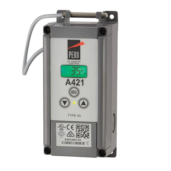
The A421 controls are available either in Type1
(NEMA), IP20 (CE), high-impact plastic enclosures
suitable for surface or DIN rail mounting (Figure 1)
or in Type 4X (NEMA), IP66 (CE) watertight, corrosion
resistant surface mount enclosures (Figure 2).
A421 Series Standard Electronic Temperature Controls Installation Instructions
Refer to the
QuickLIT website
Dimensions
Figure 1: A421 Control with Type 1 (NEMA),
IP20 Enclosure Dimensions, in. (mm)
Figure 2: A421 Control with Type 4X (NEMA),
IP66 Enclosure Dimensions, in. (mm)
1
Part No. 24-7664-3019, Rev. B
Issued November 6, 2015
for the most up-to-date version of this document.

Advertisement

Table of Contents
loading

Summary of Contents for Penn A421ABC-03C

  • Page 1 A421 Series Standard Electronic Temperature Controls Installation Instructions Part No. 24-7664-3019, Rev. B Issued November 6, 2015 A421ABC-x, A421AEC-x, A421GBF-x, A421GEF-x Refer to the QuickLIT website for the most up-to-date version of this document. Applications Dimensions IMPORTANT: Use this A421 Series Electronic Temperature Control only as an operating control.
  • Page 2 Parts Included Mounting Each A421 Control includes a Johnson Controls/ Observe the following guidelines when locating and PENN® A99 Series temperature sensor. See A99 mounting an A421 control: Series Temperature Sensors, Wiring, and Technical • Ensure that the mounting surface can support the Specifications for more information about A99 sensors.
  • Page 3 3. Position the control mounting slots over the screw Wiring heads, and then carefully tighten the mounting WARNING: Risk of Electric Shock. screws to secure the control to the surface. Disconnect or isolate all power supplies 4. When mounting the control on an uneven surface, before making electrical connections.
  • Page 4 • We recommend 22 AWG, stranded, twisted-pair IMPORTANT: When connecting an A99 sensor cable with a shield for extending sensor cable runs. with a shielded cable to an A421 Control, connect Table 1: Maximum Recommended Sensor Cable the cable shield drain lead to the COM (common) Lengths and Wire Sizes terminal on the sensor and binary input terminal block (TB3).
  • Page 5 You can also provide an independent power source for the A421 control on the TB1 terminals and then wire the TB2 relay terminals to a separate power source for switching and powering the controlled equipment circuit. Figure 3: TB2 Terminal Block Showing Connections to the Internal SPDT Relay Table 2: A421 Control Wiring Terminals and Wire Size Information Terminal...
  • Page 6 Table 2: A421 Control Wiring Terminals and Wire Size Information Terminal Label Description, Function, and Requirements Recommended Block Wire Sizes Line-Voltage SPDT Relay Common Contact: Connect power supply to 28 AWG to 12 AWG power the controlled load. 0.08 mm to 4.0 mm Connect 24 VAC (hot) for 24 VAC applications.
  • Page 7: Setup And Adjustments

    Setup and Adjustments Parameter Codes and Modes of Operation Relay Off Temperature (OFF): Select the temperature Front Panel at which the output relay de-energizes, the LC to LNO The front panel of the A421 Series Electronic relay contacts open (cutout), and the green LED goes Temperature Control has a simple LCD and a off.
  • Page 8 Anti-short cycle delay is typically used for refrigeration Temperature Setback (tSb) Select a temperature applications to allow the system pressure to equalize value for setting back the On and OFF temperature before restarting the compressor. values. When a (user-supplied) switch between the BIN and COM terminals closes: Note: When the ASd value is greater than 0, the delay interval is initiated every time that the A421 control is...
  • Page 9: A421 Control Parameter Setup Menus

    Table 4: Standard Parameter Setup Codes, Descriptions, Range of Values, and Default Values (Part 2 of 2) Parameter Parameter Description (Menu) Range of Usable Values Factory Default Code Values Shown Relay On Temperature (Basic and Advanced) -40 to 212 ºF (-40 to 100 ºC) 30 ºF Anti-Short Cycle Delay (Basic and Advanced) 0 to 12 (minutes)
  • Page 10 To exit the Basic menu and go directly into the Advanced menu, simultaneously press  and , and hold them for 5 seconds. Advanced Menu The Advanced menu allows you to change the parameter values in the Basic menu and the parameter values for the Advanced parameter codes;...
  • Page 11 Viewing and Changing Values in the Advanced When the A421 control is set up in the restricted Menu adjustment mode, the following behavior is enforced: To access the Advanced menu and view and change • The restricted temperature adjustment range is the parameter values, follow these steps: defined by the selected High Temperature Stop (HtS) and Low Temperature Stop (LtS) values.
  • Page 12: Fault Codes

    4. Disconnect power to the control and reposition the 2. Press MENU again to go to the OFF value screen. jumper to one pin (Figure 10). Reconnect power. 3. In the OFF value screen, press  or  to change the OFF value (only within the restricted adjustment range).
  • Page 13: Repair Information

    Do not attempt to repair or recalibrate the A421 temperature control. In case of a defective or improperly functioning control, contact your nearest Authorized Johnson Controls/PENN Distributor or Sales Representative. When contacting your Johnson Controls/PENN Distributor, have the model number of the control available.
  • Page 14: Ordering Information

    Temperature Control. See Table 7 and Table 8 to order A99 sensors, mounting hardware, and other accessories used to install A421 controls. Contact your nearest Johnson Controls/PENN distributor or sales representative to order these products. Table 6: A421 Series Standard Electronic Temperature Controls Selection Chart...
  • Page 15 Table 7: A99 Temperature Sensors Selection Chart (Continued) (Part 2 of 2) Product Code Description PTC Temperature Sensor: Standard probe 2 in. (5.1 cm) with 9-7/8 in. (0.25 m) high-temperature silicon A99BC-25C cable; Ambient operating temperature range: -40 to 248ºF (-40 to 100ºC) PTC Temperature Sensor: Standard probe 2 in.
  • Page 16: Technical Specifications

    Technical Specifications Table 9: A421 Series Electronic Temperature Controls Power Consumption 1.8 VA Maximum Supply Power Low-Voltage Models: 24 VAC (20 to 30 VAC), 50/60 Hz, Class 2 or Safety Extra-Low Voltage Line-Voltage Models: 110/120 or 208/230/240 VAC, 50/60 Hz Ambient Conditions Operating: Type 1 Models: -40 to 150°F (-40 to 66°C), 0 to 95% RH Non-condensing Type 4X Models: -40 to 140°F (-40 to 60°C), 0 to 95% RH Non-condensing...
  • Page 17 Building Efficiency 507 E. Michigan Street, Milwaukee, WI 53202 Johnson Controls® and PENN® are registered trademarks of Johnson Controls, Inc. in the United States of America and/or other countries. All other trademarks used herein are the property of their respective owners. © Copyright 2015 by Johnson Controls, Inc. All rights reserved.

Table of Contents