Advertisement
A19ZBA Type Temperature Control
Application
The A19ZBA temperature
control is designed for water
chiller applications. The control
has a range of 38 to 80°F (3 to
27°C) with contacts that open on
a temperature drop.
A packing nut assembly, Part
No. FTG13A-600R, (Fig. 2) is
supplied with the control for
immersion applications where a
bulb well is not required. Bulb
well No. WEL14A-600R (Fig. 3)
for immersion applications is
available, if required.
All Series A19 controls are
designed for use only as
operating controls. Where an
operating control failure
would result in personal injury
and/or loss of property, it is
the responsibility of the
installer to add devices
(safety, limit controls) or
systems (alarm, supervisory
systems) that protect against,
or warn of, control failure.
Installation
When provided, follow the
equipment manufacturer's
instructions. If instructions are
not supplied, follow the
instructions in this sheet.
!
CAUTION: Do not dent or
deform the sensitive bulb of
this control. A dent or
deformation will change the
calibration and cause the
control to cycle at a
temperature lower than the
dial setting.
Mounting
When installing the control, use
the mounting bracket as a
template and mark the location
for the two mounting screws.
© 2019 Johnson Controls
Code No. LIT-121065
Part No. 997-778, Rev. A
Drill or punch two holes and start
the mounting screws. Place the
slot in the bottom of the bracket
under the head of the lower
mounting screw. Position the
control so the top screw is in the
top slot. Tighten both screws. It
is not necessary to level the
control except for appearance.
For closed tank applications
without a bulb well, use the
FTG13A-600R packing nut. (See
Fig. 2.) Put parts over the support
tube section of the element and
place bulb in the tank. Install the
1/2 in. NPT adapter in the tank
opening and tighten. Screw the
packing nut with the retaining
washers and packing into the
adapter as shown in Fig. 2.
!
CAUTION: Turn off the
liquid supply and relieve the
pressure before installing or
removing the bulb or bulb
well.
For applications requiring a bulb
well, install the bulb well in the
tank opening. Remove the
bushing from the bulb well and
slide the bushing over the
capillary. Insert the bulb into the
bulb well and replace the bushing.
Push the bulb into position in the
bottom of the well. Tighten the set
screw in the adapter end to hold
the bulb in position.
Wiring
!
WARNING: Disconnect the
power supply before wiring
connections are made to
avoid possible electrical
shock or damage to the
equipment.
Make all wiring connections
using copper conductors only,
and in accordance with the
National Electrical Code and
local regulations.
FANs 121, 125
Temperature Controls Section A
Technical Bulletin A19ZBA
Issue Date 0119
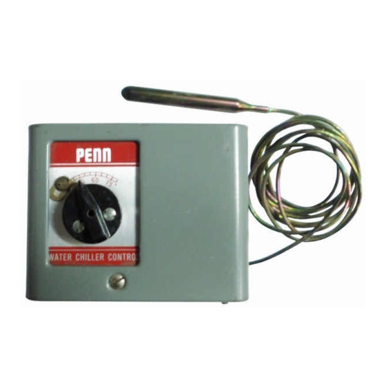
Fig. 1 -- A19ZBA-1 Temperature
Control. Note the mounting
bracket on the back of the case.
Note: Use the terminal screws
furnished (8-32 × 1/4 in. binder
head). Substitution of other
screws may cause problems in
making proper connections.
1
Advertisement
Table of Contents

Related Manuals for Penn A19ZBA


Summary of Contents for Penn A19ZBA
- Page 1 FTG13A-600R packing nut. (See immersion applications where a Fig. 2.) Put parts over the support bulb well is not required. Bulb Fig. 1 -- A19ZBA-1 Temperature well No. WEL14A-600R (Fig. 3) tube section of the element and Control. Note the mounting for immersion applications is place bulb in the tank.
- Page 2 Tighten screw "C." www.penncontrols.com ® Johnson Controls and PENN are registered trademarks of Johnson Controls in the United States of America and/or other countries. All other trademarks used herein are the property of their respective owners. © Copyright 2019 by Johnson Controls. All rights reserved.
Need help?
Do you have a question about the A19ZBA and is the answer not in the manual?
Questions and answers