
Related Manuals for Simrad ES38-18/200-18CR


Summary of Contents for Simrad ES38-18/200-18CR
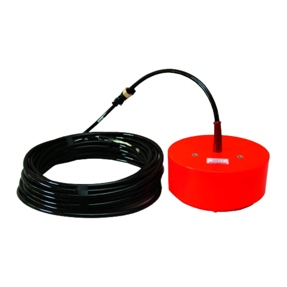
- Page 1 Installation Manual Simrad ES38-18/200-18CR Transducer Photo: Christian Ferrer / Wikimedia Commons TECHNOLOGY FOR SUSTAINABLE FISHERIES www.simrad.com...
- Page 3 Installation Manual The purpose of this manual is to provide the information, procedures and basic drawings required for the physical installation of the Simrad ES38-18/200-18CR. The manual further provides relevant descriptions and illustrations to explain the basic principles for location and noise considerations.
- Page 4 If you require maintenance or repair, contact your local dealer. You can also contact us using the following address: simrad.support@simrad.com. If you need information about our other products, visit https: //www.simrad.com. On this website you will also find a list of our dealers and distributors. Kongsberg Maritime AS www.kongsberg.com...
-
Page 5: Table Of Contents
Connecting the transducer cable to the transceiver............33 Painting the transducer face .....................34 CABLE LAYOUT AND INTERCONNECTIONS......36 Connecting ES38-18/200-18CR transducer to a 12-pin Amphenol socket .....37 12-pin Amphenol plug .....................39 Connecting the transducer to the other transceivers ............40 TRANSDUCER INSTALLATION PRINCIPLES......41 Transducer installation in a blister ...................42... - Page 6 Choose a transducer position far away from the bow thruster(s) ........54 Summary and general recommendations .................54 DRAWING FILE..............55 About the drawings in the drawing file................56 424411 ES38-18/200-18CR Dimensions.................57 424465 ES38–18/200–18CR Mounting ring ..............59 424466 ES38-18/200-18CR Clamping ring ..............61 035130 ES38-18/200-18CR Stuffing tube ...............63 820-204678 ES38-18/200-18CR Mounting arrangement..........64 436200/A...
-
Page 7: About This Manual
The outline dimensions of the ES38-18/200-18CR transducer and the relevant installation items are found in the Drawing file chapter in this manual. - Page 8 Simrad ES38-18/200-18CR Installation Manual Registered trademarks Observe the registered trademarks that apply. Windows ® is a registered trademark of Microsoft Corporation in the United States and other countries. Simrad ® , SIMRAD ® and the Simrad ® logo are either registered trademarks, or trademarks of Kongsberg Maritime AS in Norway and other countries.
-
Page 9: Simrad Es38-18/200-18Cr
Simrad ES38-18/200-18CR Simrad ES38-18/200-18CR The Simrad ES38-18/200-18CR is a "two-in-one" combi transducer designed for fishery and fishery research applications. It contains a 38 kHz split beam transducer as well as a 200 kHz single beam transducer. Both offer 18 degrees beamwidth at their nominal operational frequencies. -
Page 10: Order Information
Simrad ES38-18/200-18CR Installation Manual Order information To order the ES38-18/200-18CR, or any of the optional items provided with it, contact your local dealer. If you do not have a regular dealer, a list of all our distributors and dealers can be found on our website. - Page 11 Simrad ES38-18/200-18CR Performance specifications • Nominal frequency – 38 kHz – 200 kHz • Frequency range – 34 – 45 kHz – 190 – 230 kHz Note The following specifications are valid for the nominal frequency. • : 18 degrees Beam width •...
- Page 12 • Cable length: 20 meters • Bending radius: 185 mm Environmental requirements • Storage temperature – Maximum:+50 °C – Minimum: -20 °C • Operating temperature – Maximum:+40 °C – Minimum: -5 °C Related topics 424411 ES38-18/200-18CR Dimensions, page 57 436200/A...
-
Page 13: Support Information
Simrad ES38-18/200-18CR Support information If you need technical support for your Simrad ES38-18/200-18CR you must contact your local dealer, or one of our support departments. A list of all our offices and dealers is provided on our website. You can also contact our main support office in Norway. - Page 14 Simrad ES38-18/200-18CR Installation Manual Malaysia • : Kongsberg Maritime Malaysia Sdn. Bhd Company name • : Unit 27-5 Signature Offices, The Boulevard, Mid Valley City, Lingkaran Address Syed Putra, 59200 Kuala Lumpur, Malaysia • : +65 6411 7488 Telephone •...
-
Page 15: Transducer Handling And Maintenance
Transducer handling and maintenance Transducer handling and maintenance Topics Rules for transducer handling, page 14 Approved anti-fouling paints, page 15 Inspecting and cleaning the transducer face, page 16 Painting the transducer face, page 18 436200/A... -
Page 16: Rules For Transducer Handling
Cleaning and painting the transducer face During normal use, the transducer is subjected to biological fouling. If this marine growth is excessive, it will reduce the performance of the ES38-18/200-18CR. The transducer has not been designed with any protection against biological fouling. -
Page 17: Approved Anti-Fouling Paints
Because some paint types may be aggressive to the polyurethane in the transducer, consult our list of approved paints. The list can also be found on http://www.simrad.com. Observe the relevant instructions and safety information provided by the paint manufacturer. -
Page 18: Inspecting And Cleaning The Transducer Face
The list can also be found on http://www.simrad.com. Inspecting and cleaning the transducer face Marine growth (biological fouling) on the transducer face reduces the ES38-18/200-18CR performance. For this reason, it is important to keep the transducer face clean. Every time your vessel is in dry dock, you must remove the marine growth. At the same time, you must inspect the transducer closely for physical damage. - Page 19 Context During normal use, the transducer is subjected to biological fouling. If this marine growth is excessive, it will reduce the performance of the ES38-18/200-18CR. Whenever opportunity arise, typically when the vessel is dry docked, the transducer face must be cleaned for shells and other marine growth.
-
Page 20: Painting The Transducer Face
Painting the transducer face Marine growth (biological fouling) on the transducer face reduces the ES38-18/200-18CR performance. We recommend that you paint the transducer face immediately after installation, and then again as often as required to maintain the protection. - Page 21 Abrade the transducer surface using a sanding paper with 240 inch grit size. Do not exceed a surface roughness (R ) of 35 microns as this can influence the ES38-18/200-18CR performance. Remove all dust. Apply the primer, and let it dry.
-
Page 22: Installing The Transducer
Simrad ES38-18/200-18CR Installation Manual Installing the transducer Topics Installation summary, page 21 Designing, manufacturing and mounting the installation hardware, page 22 Installing the stuffing tube, page 23 Designing, manufacturing and mounting the steel conduit, page 25 Unpacking the transducer from its transport crate, page 27... -
Page 23: Installation Summary
Installing the transducer Installation summary The installation of the ES38-18/200-18CR transducer is a key task for successful installation of the echo sounder system. Not only will you need to penetrate the vessel’s hull, you must also to select a physical location for maximum performance and minimum acoustic and electric noise. -
Page 24: Designing, Manufacturing And Mounting The Installation Hardware
Related topics Transducer installation principles, page 41 Where to install the transducer, page 51 424411 ES38-18/200-18CR Dimensions, page 57 820-204678 ES38-18/200-18CR Mounting arrangement, page 64 424465 ES38–18/200–18CR Mounting ring, page 59 Designing, manufacturing and mounting the installation hardware Once the physical location of the transducer has been determined, the installation hardware must be designed, manufactured and mounted. -
Page 25: Installing The Stuffing Tube
The outline dimensions of the ES38-18/200-18CR transducer and the relevant installation items are found in the Drawing file chapter in this manual. Relevant outline dimensions and production drawings can be download from our website. - Page 26 Simrad ES38-18/200-18CR Installation Manual • The transducer cable must be fitted with the rubber gasket, washers and packing nut. • The installation arrangement has been approved by the relevant authority. • All relevant personnel (skilled shipyard workers, ships electricians) and relevant tools must be available.
-
Page 27: Designing, Manufacturing And Mounting The Steel Conduit
If required, all documents provided by the shipyard for the physical installation of the ES38-18/200-18CR must be approved by the vessel’s national registry and corresponding maritime authority and/or classification society. Such approval must... - Page 28 If a cable is damaged, and penetrated by water, the transducer may be damaged beyond repair. The outline dimensions of the ES38-18/200-18CR transducer and the relevant installation items are found in the Drawing file chapter in this manual. End user manuals and source drawings (normally in AutoCad format) can be downloaded from our website.
-
Page 29: Unpacking The Transducer From Its Transport Crate
Installing the transducer Unpacking the transducer from its transport crate Prior to installation, the transducer must be unpacked from its box, and placed under the mounting location. Prerequisites No special tools are required for this task. Context A transducer must always be handled as a delicate item. Wrongful actions may damage the transducer beyond repair. -
Page 30: Installing The Transducer Cable
Simrad ES38-18/200-18CR Installation Manual Installing the transducer cable When the transducer has been placed under its mounting location, the cable can be pulled through the cable gland and stuffing tube, and then through the steel conduit up to the transceiver. - Page 31 Installing the transducer Stuffing tube, penetrates the hull plating Washer Rubber gasket Packing nut Procedure Verify that the steel conduit has been finished, and that all welding has been finalized. Lower the fish tape (wire pulling tool) down from the top of the steel conduit, and through the stuffing tube.
-
Page 32: Mounting The Transducer
Simrad ES38-18/200-18CR Installation Manual Seal the top of the steel conduit with a Roxtec (or similar) multi-diameter cable sealing. Related topics 12-pin Amphenol plug, page 39 Connecting the transducer to the other transceivers, page 40 Mounting the transducer When all the preparations have been made, observe this procedure for the mounting of the transducer If required, additional and more detailed procedures must be provided by the installation ship yard. - Page 33 If required, allow the relevant maritime authority and/or classification society to inspect and approve the transducer installation. Related topics 424411 ES38-18/200-18CR Dimensions, page 57 820-204678 ES38-18/200-18CR Mounting arrangement, page 64 424465 ES38–18/200–18CR Mounting ring, page 59 436200/A...
-
Page 34: Splicing The Transducer Cable
Simrad ES38-18/200-18CR Installation Manual Splicing the transducer cable If you need to cut or lengthen the transducer cable, you must splice it correctly. This is very important, as any splice is very vulnerable for noise. Prerequisites The following items are required. -
Page 35: Connecting The Transducer Cable To The Transceiver
We recommend that all tools are demagnetized to protect your equipment. Context The ES38-18/200-18CR transducer can be used with a variety of echo sounder transceivers. These use different plugs and connectors. For specific information about the transducer connection consult the relevant echo sounder manual. -
Page 36: Painting The Transducer Face
Simrad ES38-18/200-18CR Installation Manual Painting the transducer face Marine growth (biological fouling) on the transducer face reduces the ES38-18/200-18CR performance. We recommend that you paint the transducer face immediately after installation, and then again as often as required to maintain the protection. - Page 37 Abrade the transducer surface using a sanding paper with 240 inch grit size. Do not exceed a surface roughness (R ) of 35 microns as this can influence the ES38-18/200-18CR performance. Remove all dust. Apply the primer, and let it dry.
-
Page 38: Cable Layout And Interconnections
Simrad ES38-18/200-18CR Installation Manual Cable layout and interconnections Topics Connecting ES38-18/200-18CR transducer to a 12-pin Amphenol socket, page 37 12-pin Amphenol plug, page 39 Connecting the transducer to the other transceivers, page 40 436200/A... -
Page 39: Connecting Es38-18/200-18Cr Transducer To A 12-Pin Amphenol Socket
Cable layout and interconnections Connecting ES38-18/200-18CR transducer to a 12-pin Amphenol socket The Simrad ES38-18/200-18CR transducer shall be connected to terminals through on a circular 12-pin Amphenol transducer socket. This socket is used on the General Purpose Transceiver (GPT), and on some versions of the Wide Band Transceiver (WBT). - Page 40 Simrad ES38-18/200-18CR Installation Manual We strongly recommend that you install the transducer cable in a steel conduit. Minimum cable requirements Not applicable. If you need an extension cable, contact your dealer (or Kongsberg Maritime) for support. Related topics 12-pin Amphenol plug, page 39...
-
Page 41: 12-Pin Amphenol Plug
Assemble the plug house, and tighten the rubber sleeve. Related topics Connecting ES38-18/200-18CR transducer to a 12-pin Amphenol socket, page 37 Installing the transducer cable, page 28 Splicing the transducer cable, page 32 Connecting the transducer cable to the transceiver, page 33... -
Page 42: Connecting The Transducer To The Other Transceivers
Simrad ES38-18/200-18CR Installation Manual Connecting the transducer to the other transceivers The ES38-18/200-18CR transducer can be connected to several different echo sounder transceivers. It is not practical to include all types of plugs and transceivers in this manual. Use the cable information provided for the 12-pin Amphenol plug, and connect the transducer as specified in the relevant echo sounder manual. -
Page 43: Transducer Installation Principles
Transducer installation principles Transducer installation principles Topics Transducer installation in a blister, page 42 Transducer installation in a flush mounted steel tank, page 45 Transducer installation in keel box, page 47 Transducer installation using drop keel, page 48 Smooth surface is important, page 50 Using a suitable inclination angle, page 50 436200/A... -
Page 44: Transducer Installation In A Blister
Simrad ES38-18/200-18CR Installation Manual Transducer installation in a blister In order to install a transducer with a circular housing, one recommended installation method is by means of a blister. The blister must be designed and manufactured by the installation shipyard to fit the transducer, as well as the vessel’s size and hull shape. - Page 45 Transducer installation principles Example Streamlined blister Stiffening rib Drainage holes Inclination angle Mounting ring Clamping ring Air outlet Cable service loop Stuffing tube Height: 400 mm (Minimum) Rounded corners Physical location of the blister The blister is placed on the side of the hull. The distance from the keel is a trade off between a close distance giving a turbulent flow of water in a narrow passage, and a large distance bringing the transducer higher up, and therefore more affected by the vessel roll.
- Page 46 Simrad ES38-18/200-18CR Installation Manual Keel Transducer blister Horizontal distance between the keel and the blister Vertical distance between the bottom of the keel and the blister surface Observe the horizontal and vertical distances between the keel and the transducer blister. (C + D)
-
Page 47: Transducer Installation In A Flush Mounted Steel Tank
Transducer installation principles Use a suitable toe-in angle The primary consideration for any transducer installation must be to allow laminar water flow. In most cases this is achieved by designing the blister in parallel with the keel. However, if the blister is located close to the bow, the front of the blister should have a few degrees "toe-in"... - Page 48 Simrad ES38-18/200-18CR Installation Manual Example Steel tank Water Drainage hole Cable service loop Steel tube for air outlet (much reach above water line) Stuffing tube Cable in steel conduit Mounting ring (may be part of the steel tank) Clamping ring...
-
Page 49: Transducer Installation In Keel Box
The drawing (normally in AutoCad format) can be downloaded from our website. • https://www.simrad.com Smooth surface is important Make sure that the surface of the transducer face, as well as the plating and putty around the transducer is as even and smooth as possible. -
Page 50: Transducer Installation Using Drop Keel
The vessel is then able to do reliable acoustic measurements in open sea a larger part of the year. At the bottom of the drop keel, the ES38-18/200-18CR can be installed with the transducer face flushed with the horizontal plating. A protective tank may not be necessary, since the drop keel will normally offer adequate protection. - Page 51 The drawing (normally in AutoCad format) can be downloaded from our website. • https://www.simrad.com Smooth surface is important Make sure that the surface of the transducer face, as well as the plating and putty around the transducer is as even and smooth as possible.Obstructions on these surfaces will...
-
Page 52: Smooth Surface Is Important
The smaller beam angle your transducer has, the smaller the inclination angle can be. Note Ensure that you do not mount the transducer with a negative inclination angle. This may cause turbulence on the transducer face, and reduced ES38-18/200-18CR performance. 436200/A... -
Page 53: Where To Install The Transducer
Where to install the transducer Where to install the transducer Topics Introduction to transducer location, page 52 Mount the transducer deep, page 52 Avoid protruding objects near the transducer, page 53 Keep the transducer far away from the propellers, page 53 Choose a transducer position far away from the bow thruster(s), page 54 Summary and general recommendations, page 54 436200/A... -
Page 54: Introduction To Transducer Location
Note The information here must be considered as general advice. Each ES38-18/200-18CR installation must be handled separately depending on the hull design and the other electrical and mechanical systems installed on the vessel. -
Page 55: Avoid Protruding Objects Near The Transducer
Avoid protruding objects near the transducer Objects protruding from the hull will generate turbulence and flow noise. This will reduce the ES38-18/200-18CR performance. Protruding objects may be zinc anodes, transducers or even the vessel's keel. Holes and pipe outlets are also important noise sources, as well as rough surfaces caused by bad welding. -
Page 56: Choose A Transducer Position Far Away From The Bow Thruster(S)
When in operation, the noise and cavitation bubbles created by the thruster may make your ES38-18/200-18CR Transducer useless, almost no matter where the transducer is installed. When the bow thrusters are not in operation, the tunnel creates turbulence. If your vessel is pitching, the tunnel may be filled with air or aerated water in the upper position and release this in the lower position. -
Page 57: Drawing File
Topics About the drawings in the drawing file, page 56 424411 ES38-18/200-18CR Dimensions, page 57 424465 ES38–18/200–18CR Mounting ring, page 59 424466 ES38-18/200-18CR Clamping ring, page 61 035130 ES38-18/200-18CR Stuffing tube, page 63 820-204678 ES38-18/200-18CR Mounting arrangement, page 64 436200/A... -
Page 58: About The Drawings In The Drawing File
If required, all documents provided by the shipyard for the physical installation of the ES38-18/200-18CR must be approved by the vessel’s national registry and corresponding maritime authority and/or classification society. Such approval must be obtained before the installation can begin. -
Page 59: 424411 Es38-18/200-18Cr Dimensions
Drawing file 424411 ES38-18/200-18CR Dimensions Download the source drawing from the transducer pages on https://www.simrad.com/td. 436200/A... - Page 60 Simrad ES38-18/200-18CR Installation Manual Related topics Technical specifications, page 8 Installation summary, page 21 Mounting the transducer, page 30 436200/A...
-
Page 61: 424465 Es38-18/200-18Cr Mounting Ring
Drawing file 424465 ES38–18/200–18CR Mounting ring Download the source drawing from the transducer pages on https://www.simrad.com/td. 436200/A... - Page 62 Simrad ES38-18/200-18CR Installation Manual Related topics Installation summary, page 21 Designing, manufacturing and mounting the installation hardware, page 22 Mounting the transducer, page 30 436200/A...
-
Page 63: 424466 Es38-18/200-18Cr Clamping Ring
Drawing file 424466 ES38-18/200-18CR Clamping ring Download the source drawing from the transducer pages on https://www.simrad.com/td. 436200/A... - Page 64 Simrad ES38-18/200-18CR Installation Manual 436200/A...
-
Page 65: 035130 Es38-18/200-18Cr Stuffing Tube
Drawing file 035130 ES38-18/200-18CR Stuffing tube Download the source drawing from the transducer pages on https://www.simrad.com/td. 436200/A... -
Page 66: 820-204678 Es38-18/200-18Cr Mounting Arrangement
Simrad ES38-18/200-18CR Installation Manual 820-204678 ES38-18/200-18CR Mounting arrangement Download the source drawing from the transducer pages on https://www.simrad.com/td. 436200/A... - Page 67 Drawing file Related topics Installation summary, page 21 Designing, manufacturing and mounting the installation hardware, page 22 Mounting the transducer, page 30 436200/A...
- Page 68 ......... 45 acoustic noise..........54 dimensions transducer installation ........54 about ............56 box keel ES38-18/200-18CR......... 57, 63 transducer installation ........47 ES38-18/200-18CR clamping ring drawing..61 ES38-18/200-18CR mounting ring drawing ..59 technical specifications........10 436200/A...
- Page 69 ES38-18/200-18-CR clamping ring ....61 support ............ 11 ES38-18/200-18CR mounting arrangement..64 installation ES38-18/200-18CR mounting ring ....59 clamping ring....... 44, 46–47, 49 ES38-18/200-18CR outline dimensions ....57 drawings............ 5 ES38-18/200-18CR stuffing tube ...... 63 ES38-18/200-18CR mounting arrangement..64 transducer cable ..........
- Page 70 ..........8 size transducer ..........8 ES38-18/200-18CR........57 other transceivers ES38-18/200-18CR clamping ring drawing..61 transducer connection ........40 ES38-18/200-18CR mounting ring drawing ..59 outline dimensions technical specifications........10 about ............56 slamming ES38-18/200-18CR........57 transducer ..........52 technical specifications........
- Page 71 Index connection ..........40 hull penetration........... 23 installing ..........33 wiring............40 transducer connection ES38-18/200-18CR........37 other transceivers ........40 transducer ES38-18/200-18CR mounting arrangement ........64 outline dimensions........57 stuffing tube ..........63 transducer flush mounting description ..........45 transducer handling important rules ......
- Page 72 ©2018 Kongsberg Maritime...
Need help?
Do you have a question about the ES38-18/200-18CR and is the answer not in the manual?
Questions and answers