
Related Manuals for Simrad ES38-10 - INSTALLATION REV H


Summary of Contents for Simrad ES38-10 - INSTALLATION REV H
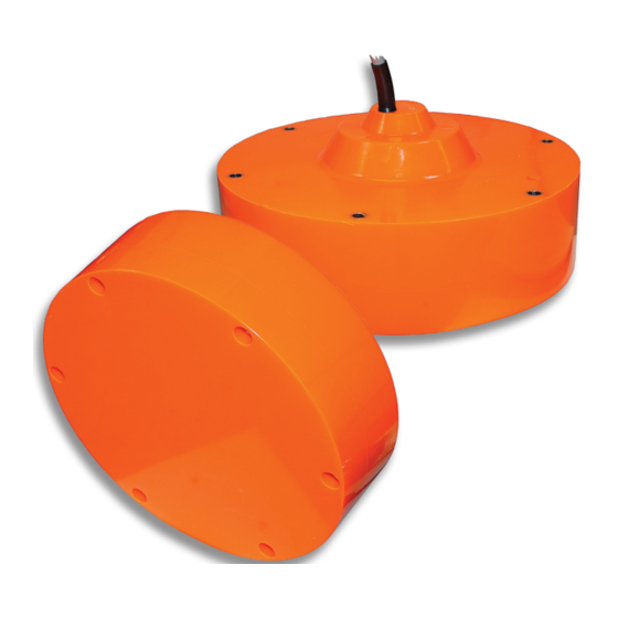
- Page 1 Installation manual Simrad ES38-10 38 kHz split-beam transducer www.SIMRAD.com M A X I M I Z I N G Y O U R P E R F O R M A N C E S E A...
- Page 3 Simrad ES38-10 Installation manual This document provides a general description of how to install the Simrad ES38-10 Split-beam transducer. The information must be regarded as general guidelines and recommendations only. The installation shipyard must design and manufacture installation hardware to fit the ES38-10 transducer on each individual vessel.
- Page 4 Simrad Horten AS. Simrad Horten AS endeavours to ensure that all information in this document is correct and fairly stated, but does not accept liability for any errors or omissions.
-
Page 5: Table Of Contents
Installation manual Table of contents INTRODUCTION ..............5 TRANSDUCER LOCATION ..........6 Go deep........................6 Vessel heave ......................6 Noise from protruding objects on the hull..............6 Boundary water layer ....................7 Propeller noise ......................7 Inclination of the transducer face ................8 Summary and general recommendation ..............8 WAYS OF MOUNTING THE TRANSDUCER ...... - Page 6 Simrad ES38-10 305176/A...
-
Page 7: Introduction
Drawing file. Technical specifications Refer to the ES38-10 Product specification. Additional parts The following items can be supplied by Simrad to facilitate installation: • Mounting ring: Order number 499–203336 • Transducer cable (for extension): Order number 642–078215... -
Page 8: Transducer Location
Simrad ES38-10 TRANSDUCER LOCATION A single answer to the question where to locate the transducer cannot be given. It depends very much on the vessel’s construction. However, there are some important guide lines. Go deep The upper water layers of the sea contain a myriad of small air bubbles created by the breaking waves. -
Page 9: Boundary Water Layer
Transducer location Boundary water layer When the vessel forces its way through the sea, the friction between the hull and the water creates a boundary layer. The thickness of the boundary layer depends upon vessel speed and the roughness of the hull. Objects protruding from the hull, and dents in the hull, disturb the flow and increase the thickness of the boundary layer. -
Page 10: Inclination Of The Transducer Face
Simrad ES38-10 outside the direct line of sight from the propeller are favourable. On small vessels with short distances it is advised to mount the transducer on that side of the keel where the propeller blades move upwards, because the propeller cavitation is strongest on the other side. - Page 11 Transducer location (CD017004Q) General recommendation for transducer location: (A) = Transducer (B) = Inclination angle (L) = Hull length at water line (M) = Maximum 1/3 of the hull length at water line (L) If the vessel hull has a bulbous bow, this may well be a good transducer location, but also here must be taken into consideration the flow pattern of the aerated water.
-
Page 12: Ways Of Mounting The Transducer
Simrad ES38-10 WAYS OF MOUNTING THE TRANSDUCER There are many different ways to mount the transducer. These are the recommended methods to mount a circular transducer. Topics Transducer blister on page 11 Box keel on page 17 Flush mounting in a steel tank on page 19... -
Page 13: Transducer Blister
Ways of mounting the transducer Transducer blister With a transducer with circular housing, one recommended installation method is by using a blister. The transducer blister must be designed and manufactured by the installation shipyard to fit the vessel’s size and hull shape. Mounting and clamping rings Circular transducers may be provided with mounting and clamping rings, or with drawings to allow for local production... - Page 14 Simrad ES38-10 Example: Large transducer The illustration below shows a typical transducer blister designed for a large transducer. Note that due to the physical size of the transducer, a U-shaped support bar (E) is used to support the transducer. The purpose of this support is to prevent the transducer from being pushed up into the blister in heavy seas.
- Page 15 Ways of mounting the transducer Example: Small transducer The illustration below shows a typical transducer blister designed for a small transducer. The same blister design principles as for a large transducer apply. (CD017010B) (A) = Streamlined blister (E) = Air outlet (B) = Mounting ring (F) = Forward (C) = Clamping ring...
- Page 16 Simrad ES38-10 Example: Medium sized transducer without clamping ring The illustration below shows a transducer blister designed for a medium sized transducers. The same blister design principles apply. Note that the transducer is mounted without a clamping ring, which makes it necessary to use a different mounting ring design.
- Page 17 Ways of mounting the transducer Common guidelines The best performance is obtained with a blister height of 40 cm or more. A streamlined shape and rounded edges reduce the flow noise. A vertical leading edge or front will guide the aerated water to the sides of the blister.
- Page 18 Simrad ES38-10 Observe the horizontal and vertical distances (X and Y) between the keel and the transducer blister. On a medium sized vessel, the horizontal distance (X) should be approximately 1 meter. The vertical distance (Y) must in general be as small as possible. This is important to prevent the keel from shadowing the transducer beam in shallow waters.
-
Page 19: Box Keel
Ways of mounting the transducer Box keel Vessels with a box keel may use this for transducer installation. The box keel is already the deepest part of the vessel. If the box keel is too narrow to accommodate the transducer, it can be widened, either symmetrically or to one side only. - Page 20 Simrad ES38-10 Example The figure below illustrates a symmetrical box keel installation. (A) = Box keel (B) = U-shaped support bar (only required on large transducers) (C) = Stuffing tube (D) = Cable in steel conduit (E) = Cable service loop...
-
Page 21: Flush Mounting In A Steel Tank
Ways of mounting the transducer Flush mounting in a steel tank Flush mounting is used on very large vessels with a hull so deep that no air bubbles are found below the hull, and on vessels operating in shallow harbours or waters, where a protruding blister can not be accepted. - Page 22 Simrad ES38-10 Example Transducer mounting in a steel tank is shown in the figure below. (CD17012A) (A) = Steel tank (B) = Water (C) = Drainage hole (D) = Cable service loop (E) = Steel tube for air outlet (F) = Stuffing tube...
-
Page 23: Acoustic Window
Acoustic window Vessels operating in arctic waters need special attention on transducer installation. Floating blocks of ice may damage even a flush mounted transducer face. For this situation Simrad offers arctic tanks in different sizes. Mounting and clamping rings Circular transducers may be provided with mounting and clamping rings, or with drawings to allow for local production of these. - Page 24 Simrad ES38-10 Example The transducer shown in the figure below is mounted inside the tank behind a strong acoustic window which could be made of polycarbonate. The tank is filled with oil. (CD017012B) (A) = Steel tank (B) = Oil...
-
Page 25: Inside The Hull
The loss varies with the distance between transducer face and the hull. The best result is obtained when the distance is half a wavelength. Consult Simrad for advice. In addition to the loss, the beam pattern is degraded, because a larger area of the hull is set into vibrations. - Page 26 Simrad ES38-10 Example The transducer shown in the figure below is mounted inside the hull. The tank is filled with oil. (CD017012C) (A) = Steel tank (B) = Oil (C) = Hull plating (D) = Cable service loop (E) = Stuffing tube (F) = Cable in steel conduit (G) = Hole for oil filling...
-
Page 27: Drop Keel
Ways of mounting the transducer Drop keel The use of a drop keel with the purpose of stabilising the vessel is well known. A drop keel is also a superior platform for echo sounder transducers. Such instrument keels have been built, mainly on research vessels, often protruding as far as three meters below the hull. -
Page 28: Retractable Transducer
Simrad ES38-10 Retractable transducer Hull units allowing the transducer to be lowered and hoisted are commonly used for horizontal looking sonars. When not in use, the transducer is retracted into a trunk. The retractable hull unit is more expensive than a blister, but on vessels with a hull where it is difficult or impossible to install a... -
Page 29: Cable Glands
Note Simrad strongly recommends that a length of conduit is fitted around transducer cable glands made of steel or bronze and extended over the water-line inside the vessel. This precaution reduces the danger of flooding in the event of gland failure and... -
Page 30: Cable Gland For Steel Hulls
The cable gland kit includes all of the necessary parts needed to install the unit except screws. Simrad recommends that a one inch steel conduit (that the transducer cable will be run through) with an inside threaded diameter of three-quarter inches is welded to the gland’s stuffing tube. -
Page 31: Cable Gland For Wood Or Grp Hulls
The cable gland kit includes all of the necessary parts needed to install the unit except screws. Simrad recommends that a one inch steel conduit (that the transducer cable will be run through) with an inside threaded diameter of three-quarter inches is attached to the gland’s packing nipple. -
Page 32: Cable Glands For Small Hulls
Simrad ES38-10 Cable glands for small hulls This cable glands made of plastic is designed for those smaller vessels that do not need to be classified. (CD17008C) (A) = Packing nut (bronze). Ensure that you do not to damage the transducer cable by tightening the packing nut too hard! -
Page 33: Cable Splicing
Cable glands Cable splicing If you need to cut the transducer cable, you must splice it correctly. Note DO NOT solder the wires together with only electrical tape for insulation, as this will result in electrical noise and reduced operational performance. To splice the cable, use a metal junction box. -
Page 34: Steel Conduit
Simrad ES38-10 STEEL CONDUIT It is strongly recommended to lay a steel conduit from the transducer’s cable gland to the echo sounder transceiver, and to pull the transducer cable through this conduit. There are two reasons for this. • First, it will make it easier at a later stage to replace the transducer. -
Page 35: Handling And Maintenance
An anti-fouling paint may be applied to the transducer face. Because some paint types may be aggressive to the polyurethane in the transducer face, please consult Simrad’s list of approved paints. Note Arctic tanks have acoustic windows made of polycarbonate. -
Page 36: Approved Anti-Fouling Paints
Simrad ES38-10 Approved anti-fouling paints This is Simrad’s list of approved antifouling paints on polyurethane transducer housing. Jotun Head office address: P.O.Box 2021, N-3248 Sandefjord, Norway Website: www.jotun.com. Racing Non-stop Safeguard Universal primer (125 micron) Antifouling SeaQuantum Ultra (125 micron) -
Page 37: Drawing File
The original installation drawings are available on PDF and AutoCad format. Visit www.simrad.com to download. In addition to the drawings available in this chapter, an additional drawing is provided on the web site. This is drawing 599–203664 describing an optional steel tank for the transducer. -
Page 38: Es38-10 Transducer Connection
Simrad ES38-10 ES38–10 transducer connection This is the termination of the transducer cable from the ES38–10 split-beam transducer to the transducer socket on the ES60 and EK60 General Purpose Transceiver Unit (GPT). The other end of the cable is permanently fixed to the transducer. -
Page 39: Outline Dimensions
Drawing file Outline dimensions Arrow indicating "forward" ø310 Cable length: 20 m Cable diameter: 10.6 ±0.5 mm ø340 ø150 ø71 ø12 ø18 ø336.5 Note: All measurements are in mm unless otherwise specified. CD017015F Page 1 of 1 The drawing is not in scale. 834-203329 Rev.B 305176/A... -
Page 40: Mounting Arrangement
Simrad ES38-10 Mounting arrangement Air outlet Steel blister, to be manufactured by the installation shipyard (Simrad dwg 830-203430) Mounting ring, may be supplied by Simrad (Simrad dwg 499-203337) FORWARD Self-locking threads WARNING: Do not lift the transducer by the cable! - Page 41 Drawing file Recommended transducer location Approx 3 deg Minimum 400 mm Min. X/4 1 - Aft starboard Air/water outlet 2 - Aft port (optional) near the echo sounder, 3 - Fore above water level 4 - Not used Screen to echo sounder chassis ø35 Steel conduit...
-
Page 42: Mounting Ring
M10 SL* (x6) Ø0.2 The self-lock threads (SL*) must be made in accordance with Simrad procedure 842-202125. Self-lock taps can be supplied by Simrad. Note: All measurements are in mm. CD017015G Page 1 of 2 The drawing is not in scale. - Page 43 Drawing file Material: St 52-3N (DIN 17100) Round steel or plate 125 ±1 21 ±1 100 +0/-0.5 45° 14 ±2 ø155 ±1 Chamfer 3 x 45° R1 (max) Note: All measurements are in mm. CD017015G Page 2 of 2 The drawing is not in scale. 871-203337 Rev.B 305176/A...
-
Page 44: Blister Assembly
Simrad ES38-10 Blister assembly Surface treatment: To avoid acoustic noise, it is very important that the surface of the blister is smooth. Avoid cracks, dents and other unevenness. 1) Sand blast after grinding to SA 2.5 2) Apply one coat of red ferric oxide prime... - Page 45 Drawing file Air vent holes R25 to 50 mm (A - A) (B - B) Depends on dead rise Minimum 400 mm Note: All measurements are in mm. CD017015H Page 2 of 2 The drawing is not in scale. 830-203430 Rev.B 305176/A...
-
Page 46: Blister Design
Simrad ES38-10 Blister design Bottom plate must be smooth and even! 1) No concavity is accepted 2) Maximum convexity is 3 mm 3) Small local hollows (max 1 mm!) can be accepted 10° 15° 30° 23° R1740 R1740 45° R525... - Page 47 Drawing file Materials: Steel plate, Fe 510 D1 (St 52-3 N), 6 and 10 mm (A - A) (B - B) Height depends on dead rise Minimum 400 mm Note: All measurements are in mm. CD017015I Page 2 of 2 The drawing is not in scale.
- Page 48 Simrad ES38-10 cavitation, 6 propeller, 7 Acoustic window EMC interference, 32 protruding objects, 6 installation, 21 ES38–10 Transducer Air bubbles, 6 connection, 36 Anti-fouling paint, 34 Outline dimensions Arctic tank drawing, 37 cleaning, 33 Flush mounting painting, 33 flush mounting, 19...
- Page 52 ISBN-10: 82-8066-073-9 ISBN-13: 978-82-8066-073-2 © 2006 Simrad Simrad Horten AS Strandpromenaden 50 Telephone: +47 33 03 40 00 P.O.Box 111 Telefax: +47 33 04 29 87 N-3191 Horten, www.simrad.com Norway simrad.sales@simrad.com...
Need help?
Do you have a question about the ES38-10 - INSTALLATION REV H and is the answer not in the manual?
Questions and answers