
Related Manuals for Simrad ES38-7


Summary of Contents for Simrad ES38-7
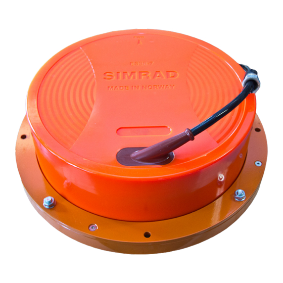
- Page 1 Installation Manual Simrad ES38-7 Split-beam transducer TECHNOLOGY FOR SUSTAINABLE FISHERIES www.simrad.com...
- Page 3 Installation Manual The purpose of this manual is to provide the information, procedures and basic drawings required for the physical installation of the Simrad ES38-7. The manual further provides relevant descriptions and illustrations to explain the basic principles for location and noise considerations.
- Page 4 If you require maintenance or repair, contact your local dealer. You can also contact us using the following address: simrad.support@simrad.com. If you need information about our other products, visit https: //www.simrad.com. On this website you will also find a list of our dealers and distributors. Kongsberg Maritime AS www.kongsberg.com...
-
Page 5: Table Of Contents
Connecting the transducer cable to the transceiver............... 38 Painting the transducer face ....................39 CABLE LAYOUT AND INTERCONNECTIONS......... 41 ES38-7 Connecting to a 12-pin Amphenol socket..............42 12-pin Amphenol plug ......................44 TRANSDUCER INSTALLATION PRINCIPLES........ 45 Transducer installation in a blister ..................46 Transducer installation in keel box .................. - Page 6 Mount the transducer at a safe distance from bow thruster(s) ..........68 Summary and general recommendations ................70 DRAWING FILE................72 About the drawings in the drawing file................. 73 393820 Dimensions ES38-7 ....................74 074544 Mounting arrangement ES38-7................77 074076 Mounting ring ES38-7 ..................... 80 404292/D...
-
Page 7: About This Manual
The outline dimensions of the ES38-7 transducer and the relevant installation items can be found in the Drawing file chapter in this manual. - Page 8 Simrad ES38-7 Installation Manual End user manuals and source drawings (normally in AutoCad format) can be downloaded from our website. • https://www.simrad.com Registered trademarks Observe the registered trademarks that apply. Windows ® is a registered trademark of Microsoft Corporation in the United States and other countries.
-
Page 9: Simrad Es38-7
Note The ES38-7 is often used as a replacement for the discontinued ES38B. If you do that, make sure that the horizontal support bar used on the ES38B is removed before you mount the ES38-7. -
Page 10: Order Information
Simrad ES38-7 Installation Manual Order information To order the ES38-7, or any of the optional items provided with it, contact your local dealer. If you do not have a regular dealer, a list of all our distributors and dealers can be found on our website. -
Page 11: Physical And Environmental Specifications
: +60° C Maximum – : -20° C Minimum • Operational temperature – : +40° C Maximum – : -5° C Minimum Related topics Simrad ES38-7, page 7 393820 Dimensions ES38-7, page 74 074076 Mounting ring ES38-7, page 80 404292/D... -
Page 12: Support Information
Simrad ES38-7 Installation Manual Support information If you need technical support for your Simrad ES38-7 you must contact your local dealer, or one of our support departments. A list of all our offices and dealers is provided on our website. You can also contact our main support office in Norway. - Page 13 Simrad ES38-7 • : Kongsberg Underwater Technology Inc / Simrad Fisheries Company name • : 19210 33rd Ave W, Suite B, Lynnwood, WA 98036, USA Address • : +1 425 712 1136 Telephone • : +1 425 712 1193 Telefax •...
- Page 14 Simrad ES38-7 Installation Manual China • : Kongsberg Maritime China Ltd Company name • : 555 Chuanqiao Road, China (Shanghai) Pilot Free Trade Zone, 201206, China Address • : +86-21-3127-9888 Telephone • : +86-21-3127-9555 Telefax • https://www.simrad.com Website • simrad.china@simrad.com...
-
Page 15: Transducer Handling And Maintenance
Transducer handling and maintenance Transducer handling and maintenance Topics Rules for transducer handling, page 14 Approved anti-fouling paints, page 15 Inspecting and cleaning the transducer face, page 17 Painting the transducer face, page 19 404292/D... -
Page 16: Rules For Transducer Handling
Cleaning and painting the transducer face During normal use, the transducer is subjected to biological fouling. If this marine growth is excessive, it will reduce the performance of the ES38-7. The transducer has not been designed with any protection against biological fouling. -
Page 17: Approved Anti-Fouling Paints
Because some paint types may be aggressive to the polyurethane in the transducer, consult our list of approved paints. The list can also be found on http://www.simrad.com. Observe the relevant instructions and safety information provided by the paint manufacturer. - Page 18 Apply 150 µm dry film thickness. • Intersmooth 7465Si SPC – : Intergard 269 Primer Apply 40 µm dry film thickness. – : Intersmooth 7465Si SPC Paint Apply 100 µm dry film thickness. The list can also be found on http://www.simrad.com. 404292/D...
-
Page 19: Inspecting And Cleaning The Transducer Face
During normal use, the transducer is subjected to biological fouling. If this marine growth is excessive, it will reduce the performance of the ES38-7. Whenever opportunity arise, typically when the vessel is dry-docked, the transducer face must be cleaned for shells and other marine growth. - Page 20 Do a thorough visual inspection of the transducer. Check for dents, scratches, holes or other damage to the surface. If you suspect damage, take a high resolution photo. Contact your dealer or the Simrad support organization for advice. If necessary, apply anti-fouling paint as described in the dedicated procedure.
-
Page 21: Painting The Transducer Face
Transducer handling and maintenance Painting the transducer face Marine growth (biological fouling) on the transducer face reduces the ES38-7 performance. We recommend that you paint the transducer face immediately after installation, and then again as often as required to maintain the protection. - Page 22 Simrad ES38-7 Installation Manual Abrade the transducer surface using a sanding paper with 240 inch grit size. Do not exceed a surface roughness (R ) of 35 microns as this can influence the ES38-7 performance. Remove all dust. Apply the primer, and let it dry.
-
Page 23: Installing The Transducer
Installing the transducer Installing the transducer Topics Installation summary, page 22 Designing, manufacturing and mounting the installation hardware, page 24 Installing the cable gland, page 25 Designing, manufacturing and mounting the steel conduit, page 27 Unpacking the transducer from its transport crate, page 29 Installing the transducer cable, page 30 Mounting the transducer, page 33 Splicing the transducer cable, page 35... -
Page 24: Installation Summary
Simrad ES38-7 Installation Manual Installation summary The installation of the ES38-7 transducer is a key task for successful installation of the echo sounder system. Not only will you need to penetrate the vessel’s hull, you must also to select a physical location for maximum performance and minimum acoustic and electric noise. - Page 25 Installing the transducer Procedure Determine the physical location of the transducer. The decision must be based on: • The vessel drawings • The shape and properties of the hull Make sure that all possible considerations are made to reduce noise. •...
-
Page 26: Designing, Manufacturing And Mounting The Installation Hardware
The outline dimensions of the ES38-7 transducer and the relevant installation items can be found in the Drawing file chapter in this manual. Relevant outline dimensions and... -
Page 27: Installing The Cable Gland
AutoCad format. Procedure Based on the vessel drawings, the physical properties of the hull, and the functionality required by the ES38-7, design the mounting hardware. Manufacture the hardware according to the relevant production standards. Mount the hardware under the vessel’s hull. - Page 28 Simrad ES38-7 Installation Manual Context These items are all provided as a part of the transducer delivery. Bushing, penetrates the hull plating Washers Rubber gasket Packing nipple Procedure Depending on the chosen installation method (blister or tank), make a hole for the bushing.
-
Page 29: Designing, Manufacturing And Mounting The Steel Conduit
Installing the transducer Designing, manufacturing and mounting the steel conduit A steel conduit is used to protect the transducer cable. The conduit serves two purposes. It will protect the cable, and shield it from electric noise. Depending on how the steel conduit is terminated over the transducer, it may also secure the watertight integrity of the vessel. - Page 30 Simrad ES38-7 Installation Manual provided by the shipyard for the physical installation of the ES38-7 must be approved by the vessel’s national registry and corresponding maritime authority and/or classification society. Such approval must be obtained before the installation can begin. The shipowner and shipyard doing the installation are responsible for obtaining and paying for such approval.
-
Page 31: Unpacking The Transducer From Its Transport Crate
Installing the transducer Unpacking the transducer from its transport crate Prior to installation, the transducer must be unpacked from its box, and placed under the mounting location. Context A transducer must always be handled as a delicate instrument. Incorrect actions may damage the transducer beyond repair. -
Page 32: Installing The Transducer Cable
Simrad ES38-7 Installation Manual Installing the transducer cable When the transducer has been placed under its mounting location, the cable can be pulled through the cable gland and bushing, and then through the steel conduit up to the transceiver. Prerequisites Before you can do this task, the following prerequisites must be met: •... - Page 33 Installing the transducer These items are all provided as a part of the transducer delivery. Bushing penetrates the hull plating Washer Rubber gasket Packing nipple Procedure Make sure that the steel conduit has been finished, and that all welding has been finalized.
- Page 34 Simrad ES38-7 Installation Manual Mount the packing nipple. Tighten the packing nipple with enough force to inhibit water penetration. When the packing nipple has been tightened, pull each cable to verify that it is fastened properly. If you can move the cable, you must tighten the packing nipple harder.
-
Page 35: Mounting The Transducer
Installing the transducer Mounting the transducer When all the preparations have been made, the transducer is mounted. If required, additional and more detailed procedures must be provided by the installation ship yard. Prerequisites The following requirements must be met before mounting the transducer: •... - Page 36 Note The ES38-7 is often used as a replacement for the discontinued ES38B. If you do that, make sure that the horizontal support bar used on the ES38B is removed before you mount the ES38-7.
-
Page 37: Splicing The Transducer Cable
Installing the transducer Splicing the transducer cable If you need to cut or lengthen the transducer cable, you must splice it correctly. This is very important, as any splice is very vulnerable for noise. Cable can be spliced using two different methods: •... -
Page 38: Splicing The Cable Using A Grounded Junction Box
Simrad ES38-7 Installation Manual Splicing the cable using a grounded junction box Context Do not solder the wires together with only electrical tape for insulation. This will result in electrical noise and reduced operational performance. Junction box Cable gland Terminal block... -
Page 39: Splicing The Cable Using A Junction Box Isolated From Vessel's Ground
Installing the transducer Splicing the cable using a junction box isolated from vessel’s ground Context Do not solder the wires together with only electrical tape for insulation. This will result in electrical noise and reduced operational performance. Do not connect the cable screen to the vessel's ground. The junction box is isolated from ship’s ground. -
Page 40: Connecting The Transducer Cable To The Transceiver
Each tool must be provided in various sizes. We recommend that all tools are demagnetized to protect your equipment. Context The ES38-7 transducer can be used with a variety of echo sounder transceivers. These use different plugs and connectors. Procedure Make sure that an ample length of the transducer cable is available for maintenance and replacement. -
Page 41: Painting The Transducer Face
Installing the transducer Painting the transducer face Marine growth (biological fouling) on the transducer face reduces the ES38-7 performance. We recommend that you paint the transducer face immediately after installation, and then again as often as required to maintain the protection. -
Page 42: Related Topics
Simrad ES38-7 Installation Manual Abrade the transducer surface using a sanding paper with 240 inch grit size. Do not exceed a surface roughness (R ) of 35 microns as this can influence the ES38-7 performance. Remove all dust. Apply the primer, and let it dry. -
Page 43: Cable Layout And Interconnections
Cable layout and interconnections Cable layout and interconnections Topics ES38-7 Connecting to a 12-pin Amphenol socket, page 42 12-pin Amphenol plug , page 44 404292/D... -
Page 44: Es38-7 Connecting To A 12-Pin Amphenol Socket
Simrad ES38-7 Installation Manual ES38-7 Connecting to a 12-pin Amphenol socket The Simrad ES38-7 is a wide band split beam transducer designed for fishery and underwater science applications. The transducer shall be connected to terminals through on a circular 12-pin Amphenol socket (Type 97-12-19S). This socket is used on some versions of the Wide Band Transceiver (WBT). - Page 45 Cable layout and interconnections Digital output Digital ground Black Cable screen Screen The cable screen must be connected to the housing on the transducer plug. Note The black wires in the transducer cable are not for grounding. You must never connect these together, and you must not connect any of them to vessel ground.
-
Page 46: 12-Pin Amphenol Plug
Splicing the cable using a grounded junction box, page 36 Splicing the cable using a junction box isolated from vessel’s ground, page 37 Connecting the transducer cable to the transceiver, page 38 ES38-7 Connecting to a 12-pin Amphenol socket, page 42 404292/D... -
Page 47: Transducer Installation Principles
Transducer installation principles Transducer installation principles Topics Transducer installation in a blister, page 46 Transducer installation in keel box, page 49 Transducer installation using an arctic tank with acoustic window, page 50 Transducer installation using drop keel, page 52 About cable glands, page 54 Using a steel conduit to protect the transducer cable, page 58 Smooth surface is important, page 60 Using a suitable inclination angle, page 60... -
Page 48: Transducer Installation In A Blister
Simrad ES38-7 Installation Manual Transducer installation in a blister In order to install a transducer with a circular housing, one recommended installation method is by means of a blister. The blister must be designed and manufactured by the installation shipyard to fit the transducer, as well as the vessel’s size and hull shape. The transducer may be added to an already existing blister that also holds other flush mounted transducers. - Page 49 Transducer installation principles Example Streamlined blister Stiffening rib Drainage holes Inclination angle Mounting ring Air outlet Cable service loop Bushing Height: 400 mm (Minimum) Rounded corners Physical location of the blister The blister is placed on the side of the hull. The distance from the keel is a trade off between a close distance giving a turbulent flow of water in a narrow passage, and a large distance bringing the transducer higher up, and therefore more affected by the vessel roll.
- Page 50 Simrad ES38-7 Installation Manual Keel Transducer blister Horizontal distance between the keel and the blister Vertical distance between the bottom of the keel and the blister surface Observe the horizontal and vertical distances between the keel and the transducer blister. (C + D)
-
Page 51: Transducer Installation In Keel Box
Make sure that the "Forward" direction on transducer points in the forward direction of the vessel. A suitable mounting ring can be provided by Kongsberg Maritime. A drawing is available for local manufacturing. The drawing (normally in AutoCad format) can be downloaded from our website. • https://www.simrad.com 404292/D... -
Page 52: Transducer Installation Using An Arctic Tank With Acoustic Window
Simrad ES38-7 Installation Manual Smooth surface is important Make sure that the surface of the transducer face, as well as the plating and putty around the transducer is as even and smooth as possible. Obstructions on these surfaces will create problems with turbulent flow, and may cause noise. - Page 53 Transducer installation principles Bushing Steel pipe(minimum1.5m above waterline) 11/4" Plug BSP Charge line , 20% propylene glycol and clean water above double bottom with easy access Air vent screw Liquid filled (20% propylene glycol and clean water) Trunk Transducer Transducer cable Bolt Bolt Clamping ring (already a part of...
-
Page 54: Transducer Installation Using Drop Keel
Transducer installation principles, page 45 Transducer installation using drop keel If your vessel is fitted with a drop keel, this is a superior platform for the ES38-7 transducer. Drop keels are often used on larger research vessels. A drop keel will frequently protrude as far as three meters below the hull. - Page 55 The drawing (normally in AutoCad format) can be downloaded from our website. • https://www.simrad.com Smooth surface is important Make sure that the surface of the transducer face, as well as the plating and putty around the transducer is as even and smooth as possible.Obstructions on these surfaces will create problems with turbulent flow, and may cause noise.
-
Page 56: About Cable Glands
Simrad ES38-7 Installation Manual About cable glands The transducer cable must pass through the hull using approved cable glands for the type of vessel in question. A steel cable gland is normally used on professional vessels with steel hulls. A bronze cable gland can be used as an option for vessels with wood or fibreglass hulls. -
Page 57: Cable Gland For Wooden And Grp Hulls
Transducer installation principles Steel conduit Bushing Washers Rubber gasket Packing nipple Cable to echo sounder (or a junction box) Note Make sure that you do not damage the transducer cable by tightening the packing nipple too hard. We recommend that the diameter of the steel conduit is chosen for best possible fit to the bushing on the cable gland. - Page 58 Simrad ES38-7 Installation Manual Packing nipple Washers Rubber gaskets Steel conduit Cable to echo sounder (or a junction box) Note Make sure that you do not damage the transducer cable by tightening the packing nipple too hard. Related topics Transducer installation principles,...
-
Page 59: Cable Glands For Small Hulls
Transducer installation principles Cable glands for small hulls For smaller vessels that do not need to be classified, a different cable gland can be used. Packing nipple Rubber gaskets Plastic disc Rubber gaskets Bushing Backing nut Backing washer O-ring O-ring Cable to echo sounder (or a junction box) Note... -
Page 60: Part Numbers For Cable Gland Kits
It is strongly recommended to lay a steel conduit from the cable gland above the transducer to the ES38-7 transceiver, and to pull the transducer cable through this conduit. The conduit serves two purposes. It will protect the cable, and shield it from electric noise. Depending on how the steel conduit is terminated over the transducer, it may also secure the watertight integrity of the vessel. - Page 61 Transducer installation principles Steel conduit quality and shielding The steel conduit must be unbroken and watertight from the transducer to above the water line. From there, the cable can be pulled further, or a junction box can be installed to facilitate further connections.
-
Page 62: Smooth Surface Is Important
1 ° inclination angle. The smaller beam angle your transducer has, the smaller the inclination angle can be. Note Ensure that you do not mount the transducer with a negative inclination angle. This may cause turbulence on the transducer face, and reduced ES38-7 performance. 404292/D... -
Page 63: Using Self-Locking Taps
Transducer installation principles Related topics Transducer installation principles, page 45 Using self-locking taps The mounting rings delivered by Kongsberg Maritime are fitted with self-locking threads. Normal screws are designed to be loosened. It is however important to avoid accidental loosening, especially when the installation is subjected to dynamic stress. For this reason, additional locking devices are required. - Page 64 Simrad ES38-7 Installation Manual • Modified profile with ramp surface in the direction of stress • 30° ramp surface provides self-locking effect • Easy assembly • No assembly errors (forgetting the locking device) possible • Use the standard external threads (screws) with tolerance class "medium"...
- Page 65 Transducer installation principles Note In case of tapping through holes it is important that the profile of the Emuge self-lock threads is in the correct direction compared with the entering direction of the bolt. Gauge Use Emuge self-lock gauges. Note that the gauge must be used in the correct direction. Self-lock taps provided by Kongsberg Maritime Several self-lock taps are on stock at Kongsberg Maritime, and can be ordered from us.
-
Page 66: Where To Install The Transducer
Simrad ES38-7 Installation Manual Where to install the transducer Topics Introduction to transducer location, page 65 Mount the transducer deep, page 65 Avoid protruding objects near the transducer, page 66 Mount the transducer at forward part of hull to minimize the effects from the flow boundary... -
Page 67: Introduction To Transducer Location
Related topics Where to install the transducer, page 64 Mount the transducer deep In order to achieve the best possible ES38-7 performance, mount the transducer as deep as possible under the vessel’s hull. There are several reasons for this recommendation. -
Page 68: Avoid Protruding Objects Near The Transducer
Simrad ES38-7 Installation Manual Transmitting in air The transducer must never be lifted free of the water surface. If the transducer is activated when out of the water it may be damaged beyond repair. Mounting the transducer at a deep position on the hull will in normally prevent this. -
Page 69: Mount The Transducer At Forward Part Of Hull To Minimize The Effects From The Flow Boundary Water Layer
Where to install the transducer Mount the transducer at forward part of hull to minimize the effects from the flow boundary water layer The upper water layers of the sea contain a myriad of small air bubbles created by the breaking waves. -
Page 70: Keep The Transducer Far Away From The Propellers
When in operation, the noise and cavitation bubbles created by the thruster may make your ES38-7 Split-beam transducer useless, almost no matter where the transducer is installed. When the bow thrusters are not in operation, the tunnel creates turbulence. If your vessel is pitching, the tunnel may be filled with air or aerated water in the upper position and release this in the lower position. - Page 71 Where to install the transducer Related topics Where to install the transducer, page 64 404292/D...
-
Page 72: Summary And General Recommendations
Simrad ES38-7 Installation Manual Summary and general recommendations Some of the installation guidelines provided for transducer location may be conflicting. For this reason, each vessel must be treated individually in order to find the best compromise. In general, the most important factor is to avoid air bubbles in front of the transducer face. - Page 73 Where to install the transducer If the vessel hull has a bulbous bow, this may well be a good transducer location, but also in this case the flow pattern of the aerated water must be taken into consideration. The foremost part of the bulb is often a good location. Thruster Transducer location This applies to the vessel in normal trim and speed.
-
Page 74: Drawing File
Simrad ES38-7 Installation Manual Drawing file Topics About the drawings in the drawing file, page 73 393820 Dimensions ES38-7, page 74 074544 Mounting arrangement ES38-7, page 77 074076 Mounting ring ES38-7, page 80 404292/D... -
Page 75: About The Drawings In The Drawing File
Drawing file About the drawings in the drawing file Relevant drawings related to the installation and/or maintenance of the ES38-7 are provided for information purposes only. Note These drawings are provided only for information and planning purposes. Information may be omitted. Observe the source drawings for additional details. -
Page 76: 393820 Dimensions Es38-7
Simrad ES38-7 Installation Manual 393820 Dimensions ES38-7 Download the source drawing from the transducer pages on https://www.simrad.com/td. 404292/D... - Page 77 Drawing file 404292/D...
- Page 78 Simrad ES38-7 Installation Manual Related topics Physical and environmental specifications, page 9 Drawing file, page 72 404292/D...
-
Page 79: 074544 Mounting Arrangement Es38-7
Drawing file 074544 Mounting arrangement ES38-7 Download the source drawing from the transducer pages on https://www.simrad.com/td. 404292/D... - Page 80 Simrad ES38-7 Installation Manual 404292/D...
- Page 81 Drawing file Related topics Drawing file, page 72 404292/D...
-
Page 82: 074076 Mounting Ring Es38-7
Simrad ES38-7 Installation Manual 074076 Mounting ring ES38-7 Download the source drawing from the transducer pages on https://www.simrad.com/td. 404292/D... - Page 83 Drawing file Related topics Physical and environmental specifications, page 9 Order information, page 8 404292/D...
- Page 84 65, 68 propellers............ 68 acoustic window transducer ........... 68 transducer installation ........50 circular socket ES38-7 transducer connection ......42 amphenol socket classification society ES38-7 transducer connection ......42 approval of installation drawings ..... 5, 73 anti-fouling paints approved ............
- Page 85 ES38-7 mounting arrangement......77 concept ............60 ES38-7 mounting ring........80 information ES38-7 outline dimensions ....... 74 support ............10 drawings install transducer about ............73 in forward part of hull ........67 approval ..........5, 73 installation creating ...........
- Page 86 Simrad ES38-7 Installation Manual Kongsberg Maritime part number support ............10 optional items ..........8 transducer ............. 8 physical and environmental specifications weight ............9 physical and environmental specificationss manual outline dimensions........... 9 purpose ............. 1, 5 procedure target audience ..........5 connecting the transducer cable......
- Page 87 Index ES38-7 mounting ring........80 steel conduit ..........58 physical and environmental specifications ....9 transducer connection slamming ES38-7 ............42 transducer ........... 66 transducer ES38-7 smooth surface description ............ 7 transducer ......... 48, 50–51, 53, 60 outline dimensions......... 74...
- Page 88 ©2019 Kongsberg Maritime...
Need help?
Do you have a question about the ES38-7 and is the answer not in the manual?
Questions and answers