
Related Manuals for Simrad ES38-18


Summary of Contents for Simrad ES38-18
- Page 1 Installation Manual Simrad ES38-18/200-18C Combi transducer TECHNOLOGY FOR SUSTAINABLE FISHERIES www.simrad.com...
- Page 3 Installation manual The purpose of this manual is to provide the information, procedures and basic drawings required for the physical installation of the Simrad ES38-18/200–18C Combi transducer. The manual further provides relevant descriptions and illustrations to explain the basic principles for location and noise considerations.
- Page 4 If you require maintenance or repair, contact your local dealer. You can also contact us using the following address: simrad.support@simrad.com. If you need information about our other products, visit http: //www.simrad.com. On this website you will also find a list of our dealers and distributors. Kongsberg Maritime AS www.kongsberg.com...
-
Page 5: Table Of Contents
Splicing the transducer cable ....................32 Connecting the transducer cable to the transceiver............... 33 CABLE LAYOUT AND INTERCONNECTIONS......... 35 Transducer ES38-18/200-18C connection to a GPT transducer socket........ 36 GPT Transducer plug ......................38 Transducer ES38-18/200–18C connection to other transceivers.......... 39 TRANSDUCER INSTALLATION PRINCIPLES........ - Page 6 Stay far away from the propellers..................57 Choose a position far away from the bow thruster(s) ............57 Summary and general recommendations ................58 DRAWING FILE................59 About the drawings in the drawing file................. 60 ES38-18/200-18C outline dimensions .................. 61 404776/A...
-
Page 7: About This Manual
The shipowner and shipyard doing the installation are responsible for obtaining and paying for such approval. Simrad will accept no responsibility for any damage or injury to the system, vessel or personnel caused by equipment that has been incorrectly installed or maintained, or by drawings, instructions or procedures that have not been prepared by us. - Page 8 Simrad ES38-18/200–18C Installation manual Applicable generic outline dimension and/or productions drawings are provided in the Drawing file chapter. Drawings may also be downloaded in PDF and/or DWG formats from our website: http://www.simrad.com. Registered trademarks Observe the registered trademarks that apply.
-
Page 9: Simrad Es38-18/200-18C
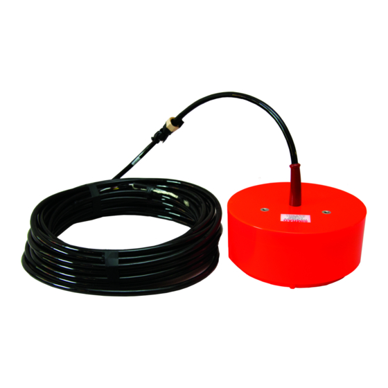
Simrad ES38-18/200-18C Simrad ES38-18/200-18C The Simrad ES38-18/200-18C is a "two-in-one" combi transducer designed for fishery and fishery research applications. It contains a 38 kHz split beam transducer as well as a 200 kHz single beam transducer. Both offer 18 degrees beamwidth at their nominal operational frequencies. -
Page 10: Order Information
Simrad ES38-18/200–18C Installation manual Order information To order the ES38-18/200–18C, or any of the optional items provided with it, contact your local dealer. If you do not have a regular dealer, a list of all our distributors and dealers can be found on our website. - Page 11 Simrad ES38-18/200-18C – : 200 kHz High • Frequency range – : 34 to 45 kHz – : 190 to 230 kHz High The following specifications are valid for the nominal frequency. • : 18 degrees Beamwidth • Figure of merit –...
-
Page 12: Support Information
Min. Support information If you need technical support for your Simrad ES38-18/200–18C you must contact your local dealer, or one of our support departments. A list of all our offices and dealers is provided on our website. You can also contact our main support office in Norway. - Page 13 : +34 966 852 304 Telefax • http://www.simrad.es Website • simrad.spain@simrad.com E-mail address • : Kongsberg Underwater Technology Inc / Simrad Fisheries Company name • : 19210 33rd Ave W, Lynnwood, WA 98036, USA Address • : +1 425 712 1136 Telephone •...
-
Page 14: Rules For Transducer Handling
Simrad ES38-18/200–18C Installation manual Rules for transducer handling To secure long life and accurate results, each transducer must be handled correctly. Transducer handling A transducer must always be handled as a delicate item. Wrongful actions may damage the transducer beyond repair. -
Page 15: Approved Anti-Fouling Paints
Rules for transducer handling Painting the transducer face Anti-fouling paint may be applied to the transducer face. Because some paint types may be aggressive to the polyurethane in the transducer, consult our list of approved paints. Special rules for acoustic windows Arctic tanks have acoustic windows made of polycarbonate. - Page 16 Simrad ES38-18/200–18C Installation manual • Intersmooth 360 Ecoloflex SPC • Micron Extra 404776/A...
-
Page 17: Installing The Transducer
Installing the transducer Installing the transducer Topics Installation summary, page 16 Designing manufacturing and mounting the installation hardware, page 17 Installing the stuffing tube, page 19 Designing, manufacturing and mounting the steel conduit, page 21 Unpacking the transducer from its transport box, page 22 Installing the transducer cable, page 24 Mounting the transducer on a steel hull, page 26 Mounting the transducer on a wooden or polyester hull, page 28... -
Page 18: Installation Summary
Simrad ES38-18/200–18C Installation manual Installation summary The installation of the ES38-18/200–18C transducer is a key task for successful installation of the echo sounder system. Not only will you need to penetrate the vessel’s hull, you must also to select a physical location for maximum performance and minimum acoustic and electric noise. -
Page 19: Designing Manufacturing And Mounting The Installation Hardware
Installing the transducer Design, manufacture and mount the steel conduit for the transducer cable. Unpack the transducer from its transport crate. Position the transducer under the mounting location. Pull the transducer cable up through the steel conduit. Tighten the packing nut on the cable gland properly to avoid leaks. 10 Mount the transducer. - Page 20 Obstructions on these surfaces may create problems with noise. If relevant, allow the relevant maritime authority and/or classification society to inspect and approve the design and installation. Related topics Installation summary, page 16 ES38-18/200-18C outline dimensions, page 61 404776/A...
-
Page 21: Installing The Stuffing Tube
Installing the transducer Installing the stuffing tube In order to secure the vessel’s watertight integrity, it is extremely important that the transducercable penetrates the ship’s hull in a safe manner. One suggested method is to use a stuffing tube and a cable gland. The cable gland consists of a rubber gasket, washers and a packing nut. - Page 22 Simrad ES38-18/200–18C Installation manual Further requirements Before you can pull the transducer cable through the cable gland, the steel conduit must be installed. Related topics Installation summary, page 16 404776/A...
-
Page 23: Designing, Manufacturing And Mounting The Steel Conduit
Installing the transducer Designing, manufacturing and mounting the steel conduit A high quality transducer cable is used between the transducer and the transceiver. In order to ensure a safe installation, a steel conduit must be installed for this cable. The conduit serves two purposes. -
Page 24: Unpacking The Transducer From Its Transport Box
Related topics Installation summary, page 16 Unpacking the transducer from its transport The ES38-18/200–18C transducer is shipped in a cardboard box. Prior to installation, the transducer must be unpacked from the cardboard box, and placed under the mounting location. Prerequisites •... - Page 25 Installing the transducer Context A transducer must always be handled as a delicate item. Wrongful actions may damage the transducer beyond repair. Observe these rules: • Do not activate the transducer when it is out of the water. • Do not lift the transducer by the cable. •...
-
Page 26: Installing The Transducer Cable
Simrad ES38-18/200–18C Installation manual Installing the transducer cable When the transducer has been placed under the mounting location, the cable can be pulled through the cable gland and stuffing tube, and then through the steel conduit up to the transceiver. - Page 27 If you can move the cable, you must tighten the packing nut harder. Related topics Installation summary, page 16 Splicing the transducer cable, page 32 Connecting the transducer cable to the transceiver, page 33 Transducer ES38-18/200-18C connection to a GPT transducer socket, page 36 404776/A...
-
Page 28: Mounting The Transducer On A Steel Hull
Mounting the transducer on a steel hull When all the preparations have been made, observe this procedure for the mounting of the ES38-18/200–18C transducer. If required, additional - and more detailed - procedures must be provided by the installation shipyard. - Page 29 Installing the transducer Threaded rod with suitable diameter and length, welded to the bottom of the fairing Washer Transducer cable Hull Fill with suitable filling compound (putty) to reduce flow noise Procedure Lift the transducer up into is location, and align the holes on the transducer with the threaded rods welded to the fairing.
-
Page 30: Mounting The Transducer On A Wooden Or Polyester Hull
Mounting the transducer on a wooden or polyester hull When all the preparations have been made, observe this procedure for the mounting of the ES38-18/200–18C transducer. If required, additional - and more detailed - procedures must be provided by the installation shipyard. Prerequisites •... - Page 31 Installing the transducer The force of the water when the hull falls down may push the transducer up, and may cause damage both to the transducer and to its mounting. Note Kongsberg Maritime AS takes no responsibility for any damages to the transducer, the cable or the mounting arrangement, caused by slamming.
-
Page 32: Mounting The Transducer On A Blister Or Drop Keel
Mounting the transducer on a blister or drop keel When all the preparations have been made, observe this procedure for the mounting of the ES38-18/200–18C transducer. If required, additional - and more detailed - procedures must be provided by the installation shipyard. Prerequisites •... - Page 33 Installing the transducer • Loctite 270 (permanent high-strength threadlocker) Context This installation arrangement assumes that you can access the inside of the blister or drop keel to mount the nuts. If this is not the case, the transducer transducer must be mounted with threaded steel rods welded to the bottom of the blister.
-
Page 34: Splicing The Transducer Cable
Related topics Installation summary, page 16 ES38-18/200-18C outline dimensions, page 61 Streamlined housing mounted externally on a steel hull, page 41 Streamlined housing mounted externally on a wooden or polyester hull, page 44 Transducer installation under a blister, page 47... -
Page 35: Connecting The Transducer Cable To The Transceiver
All necessary tools and instruments required must be available. Context The ES38-18/200–18C transducer can be used with a variety of echo sounder transceivers. These use different plugs and connectors. For specific information about the transducer connection consult the relevant echo sounder manual. - Page 36 Mount the transducer plug - or make the connection to the transceiver - as described in the relevant echo sounder installation manual. Related topics Installation summary, page 16 Installing the transducer cable, page 24 Transducer ES38-18/200-18C connection to a GPT transducer socket, page 36 GPT Transducer plug, page 38 404776/A...
-
Page 37: Cable Layout And Interconnections
Cable layout and interconnections Cable layout and interconnections Topics Transducer ES38-18/200-18C connection to a GPT transducer socket, page 36 GPT Transducer plug, page 38 Transducer ES38-18/200–18C connection to other transceivers, page 39 404776/A... -
Page 38: Transducer Es38-18/200-18C Connection To A Gpt Transducer Socket
Simrad ES38-18/200–18C Installation manual Transducer ES38-18/200-18C connection to a GPT transducer socket The ES38-18/200-18C transducer shall be connected to terminals through on a GPT type transducer socket. This socket is used on both the General Purpose Transceiver (GPT) and the Wide Band Transceiver (WBT) units. - Page 39 Cable layout and interconnections The table and illustration show the termination of the transducer cable from a ES38-18/200-18C transducer to a GPT type transducer socket. The other end of the cable is permanently fixed to the transducer. The cable screen must be connected to the housing on the transducer plug and to terminal If a junction box is used to extend the transducer cable, the screen must be connected to the cable glands on the junction box.
-
Page 40: Gpt Transducer Plug
Assemble the plug house, and tighten the rubber sleeve. Related topics Transducer ES38-18/200-18C connection to a GPT transducer socket, page 36 Connecting the transducer cable to the transceiver, page 33 404776/A... -
Page 41: Transducer Es38-18/200-18C Connection To Other Transceivers
Cable layout and interconnections Transducer ES38-18/200–18C connection to other transceivers The ES38-18/200–18C transducer can be connected to several different echo sounder transceivers. It is not practical to include all types of plugs and transceivers in this manual. Use the cable information provided for the GPT transducer plug, and connect the transducer as specified in the relevant echo sounder manual. -
Page 42: Transducer Installation Principles
Simrad ES38-18/200–18C Installation manual Transducer installation principles Topics Streamlined housing mounted externally on a steel hull, page 41 Streamlined housing mounted externally on a wooden or polyester hull, page 44 Transducer installation under a blister, page 47 Transducer installation using drop keel, page 51... -
Page 43: Streamlined Housing Mounted Externally On A Steel Hull
Transducer installation principles Streamlined housing mounted externally on a steel hull When a streamlined transducer is mounted under a steel hull, you must design, manufacture and install a fairing. The fairing must be made by the shipyard, and it shall placed between the transducer and the hull. - Page 44 Simrad ES38-18/200–18C Installation manual Example Fairing Cable service loop Filling compound (putty) Inclination angle Air outlet Threaded rod welded to the bottom of the fairing Steel conduit Stuffing tube Washer (normally inserted on the transducer cable) Rubber gasket (normally inserted on the transducer cable)
- Page 45 Transducer installation principles Use a suitable inclination angle In order to ensure laminar flow, the transducer face may be tilted slightly upwards in relation to the water flow. This allows the flowing water to meet the face directly, and assures laminar flow. Use a suitable toe-in angle The primary consideration for any transducer installation must be to allow laminar water flow.
-
Page 46: Streamlined Housing Mounted Externally On A Wooden Or Polyester Hull
Simrad ES38-18/200–18C Installation manual Streamlined housing mounted externally on a wooden or polyester hull When a streamlined transducer is mounted under a wooden or polyester hull, you must design, manufacture and install a fairing. The fairing must be made by... - Page 47 Transducer installation principles Example Fairing Cable service loop Filling compound (putty) Inclination angle Air outlet Shim (wood) Tarred felt Threaded rod with nuts and washers, or bolt Steel conduit Stuffing tube Washer (normally inserted on the transducer cable) Rubber gasket (normally inserted on the transducer cable) Packing nut (normally inserted on the transducer cable) 404776/A...
- Page 48 Simrad ES38-18/200–18C Installation manual Smooth surface is important Ensure that the surface of the transducer face, the hull plating and putty around the transducer is as even and smooth as possible. Obstructions on these surfaces will create problems with turbulent flow.
-
Page 49: Transducer Installation Under A Blister
Transducer installation principles Transducer installation under a blister A recommended method for transducer installation is by using a blister. The transducer blister must be designed and manufactured by the installation shipyard to fit the relevant transducers, as well as the vessel’s size and hull shape. Creating a blister for a single externally mounted streamlined transducer is not relevant. - Page 50 Simrad ES38-18/200–18C Installation manual Example Streamlined blister Streamlined transducer mounted under the blister Note that it is located behind the flush mounted circular transducer. Circular transducer flush mounted in the blister Inclination angle Cable service loop Stuffing tube Height minimum 400 mm...
- Page 51 Transducer installation principles Keel Transducer blister Horizontal distance between the keel and the blister Vertical distance between the bottom of the keel and the blister surface Observe the horizontal and vertical distances ( ) between the keel and the transducer blister. On a medium sized vessel, the horizontal distance ( ) should be approximately 1...
- Page 52 Simrad ES38-18/200–18C Installation manual Keel Blister Toe-in angle The angle must be chosen to allow for most efficient water flow. It will vary with the location of the transducer; the depth below the hull, the distance from the bow, and the distance to the keel.
-
Page 53: Transducer Installation Using Drop Keel
Transducer installation principles Transducer installation using drop keel If your vessel is fitted with a drop keel, this is a superior platform for the ES38-18/200–18C transducer. Drop keels are often used on larger research vessels. A drop keel will frequently protrude as far as three meters below the hull. - Page 54 Simrad ES38-18/200–18C Installation manual Example Tubular flow Laminar flow Air bubbles in the water Drop keel (extended) Several transducers can be installed at the bottom of the drop keel Smooth surface is important Ensure that the surface of the transducer face, the hull plating and putty around the transducer is as even and smooth as possible.
-
Page 55: Smooth Surface Is Important
Transducer installation principles Smooth surface is important Ensure that the surface of the transducer face, the hull plating and putty around the transducer is as even and smooth as possible. Obstructions on these surfaces will create problems with turbulent flow. Mounting screws or bolts must not be extruding from the transducer or the area immediately around it. -
Page 56: Use A Suitable Inclination Angle
Simrad ES38-18/200–18C Installation manual Related topics Streamlined housing mounted externally on a steel hull, page 41 Streamlined housing mounted externally on a wooden or polyester hull, page 44 Mounting the transducer on a steel hull, page 26 Mounting the transducer on a wooden or polyester hull, page 28... -
Page 57: Where To Install The Transducer
Where to install the transducer Where to install the transducer Topics Introduction, page 56 Mount the transducer deep, page 56 Avoid protruding objects, page 57 Stay far away from the propellers, page 57 Choose a position far away from the bow thruster(s), page 57 Summary and general recommendations, page 58 404776/A... -
Page 58: Introduction
Mount the transducer deep In order to achieve the best possible ES38-18/200–18C performance, mount the transducer as deep as possible under the vessel’s hull. Consider the situations when the vessel is unloaded, and when it is pitching in heavy seas. -
Page 59: Avoid Protruding Objects
Choose a position far away from the bow thruster(s) Bow thruster propellers are extremely noisy. When in operation, the noise and cavitation bubbles created by the thruster may make your ES38-18/200–18C system useless, almost no matter where the transducer is installed. 404776/A... -
Page 60: Summary And General Recommendations
Simrad ES38-18/200–18C Installation manual And when not in operation, the tunnel creates turbulence. If your vessel is pitching, the tunnel may be filled with air or aerated water in the upper position and release this in the lower position. In general, all transducers must therefore be placed well away from the bow thruster. In most cases, a location forward of the bow thruster is advantageous. -
Page 61: Drawing File
Drawing file Drawing file Topics About the drawings in the drawing file, page 60 ES38-18/200-18C outline dimensions, page 61 404776/A... -
Page 62: About The Drawings In The Drawing File
Simrad ES38-18/200–18C Installation manual About the drawings in the drawing file Drawings relevant for ES38-18/200–18C installation are provided. Note These drawings are for information and planning purposes only. They are not in scale. All dimensions are in mm unless otherwise is noted. The original installation drawings are available on PDF and/or AutoCad's DWG format. -
Page 63: Es38-18/200-18C Outline Dimensions
Drawing file ES38-18/200-18C outline dimensions Drawing 384703 (Three pages) 404776/A... - Page 64 Simrad ES38-18/200–18C Installation manual 404776/A...
- Page 65 Drawing file Related topics Designing manufacturing and mounting the installation hardware, page 17 Mounting the transducer on a steel hull, page 26 Mounting the transducer on a wooden or polyester hull, page 28 Mounting the transducer on a blister or drop keel, page 30 404776/A...
- Page 66 ©2015 Kongsberg Maritime...
Need help?
Do you have a question about the ES38-18 and is the answer not in the manual?
Questions and answers