
Subscribe to Our Youtube Channel
Related Manuals for Lenze MOBILE DCU


Summary of Contents for Lenze MOBILE DCU
- Page 1 Mobile Drive EDSMDAG .Rtù Hardware Manual MOBILE EMDxGxxxxxxxxxxx1x MOBILE DCU MOBILE PSU MOBILE DCU PSU MOBILE DCU S Ò...
- Page 2 0Fig. 0Tab. 0...
-
Page 3: Table Of Contents
............General safety and application notes for Lenze MOBILE devices . - Page 4 ......... . . Connections of MOBILE DCU, PSU, DCU PSU .
-
Page 5: About This Documentation
This manual contains the complete information on the intended use of components of the MOBILE product platform in mobile applications in or on vehicles. Tip! Information and tools concerning the Lenze products can be found in the download area at www.lenze.com... -
Page 6: Document History
About this documentation Document history Document history Material number Version Description .Rtù 04/2018 TD29 Revision of the Hardware Manual to the hardware version x1x 13473426 10/2014 TD15 Corrections 13473426 10/2014 TD15 First edition Conventions used This documentation uses the following conventions to distinguish between different types of information: Spelling of numbers Decimal separator... -
Page 7: Terms And Abbreviations Used
About this documentation Terms and abbreviations used Terms and abbreviations used Term Description AppC Application Controller Controller Area Network or electric circuit for CAN with its own current supply Direct current DC/AC inverter Drive Control Unit DCU PSU Combined device Double inverter Inverter for two motors or two drives Single inverter... - Page 8 About this documentation Terms and abbreviations used Term Description DC−bus level Energy storage between rectification and DCAC conversion, for one or more controllers DC−bus connection, DC−bus Interconnection of several inverters on the DC−bus level operation Ò EDSMDAG EN 2.0...
-
Page 9: Notes Used
About this documentation Notes used Notes used The following pictographs and signal words are used in this documentation to indicate dangers and important information: Safety instructions Structure of safety instructions: Danger! (characterises the type and severity of danger) Note (describes the danger and gives information about how to prevent dangerous situations) Pictograph and signal word Meaning... -
Page 10: Safety Instructions
– The procedural notes and circuit details described in the documentation are only proposals. It is up to the user to check whether they can be transferred to the particular applications. Lenze Schmidhauser does not accept any liability for the suitability of the procedures and circuit proposals described. - Page 11 Safety instructions General safety and application notes for Lenze MOBILE devices The devices and related components can − depending on the degree of protection − ƒ have live, movable or rotating parts during operation. – Surfaces can be hot. – Do not remove required covers.
- Page 12 Safety instructions General safety and application notes for Lenze MOBILE devices Electrical connection When working on live devices, observe the applicable national regulations for the prevention of accidents and technical measures for occupational safety and health. The electrical installation must be carried out according to the appropriate regulations (e.g.
-
Page 13: Residual Hazards
Safety instructions Residual hazards Residual hazards Protection of persons Switch off the high voltage on−board voltage completely before working on the ƒ devices. Before working on the device, check whether all power terminals are deenergised ƒ because – after disconnection, the power terminals U, V and W remain live for at least 5 minutes depending on the system. -
Page 14: Product Description
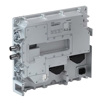
Product description System overview Product description System overview The components from the MOBILE modular system are used to realise auxiliary unit applications in commercial vehicles by means of electric motors: MOBILE DCU PSU DCU S Device type Double inverter for two motors ˘... - Page 15 Product description System overview MOBILE DCU 2× EMDAG013a Fig. 1 MOBILE DCU (EMDxG2...) Connections and elements Info ^ 43 Connection of water cooling ^ 54 Connection of HV system 800 V DC Connection of motor A ^ 55 Connection of motor B...
- Page 16 Product description System overview MOBILE PSU X21/B- X21/B+ EMDAG012a Fig. 2 MOBILE PSU (EMDxG3...) Connections and elements Info ^ 43 Connection of water cooling ^ 54 Connection of HV system 400 V DC or 800 V DC ^ 57 X21/B+ LV mains 14 V DC or 28 V DC X21/B−...
- Page 17 Product description System overview MOBILE DCU PSU X21/B- X21/B+ EMDAG011a Fig. 3 MOBILE DCU/PSU (EMDxG4...) Connections and elements Info ^ 43 Connection of water cooling ^ 54 Connection of HV system 400 V DC or 800 V DC ^ 55...
- Page 18 Product description System overview MOBILE DCU S EMDAG028b Fig. 4 MOBILE DCU S (EMDxG5...) Connections and elements Info ^ 43 Connection of water cooling ^ 63 Vehicle interface, connection of control voltage, control signals, CAN ^ 62 Connection of HV on−board supply system 800 V DC...
-
Page 19: Device Features
Product description Device features Device features Device feature EMDAG2... EMDAG3... EMDAG4... EMDAG5... Power range 7.5 ... 60 2.8 ... 5.6 2.8 ... 60 7.5 ... 22 (Peak Power) DC/AC inverter ˘ DC/DC converter ˘ ˘ Approval acc. to ECE R10 Degree of protection IP6K9K IP6K9K... -
Page 20: Identification
Product description Identification Identification Each device is marked with a clear nameplate. The following data on the nameplate serves to identify each device: Type designation (product key) ƒ Technical data ƒ Serial number (SN) ƒ ‚ ƒ „ MOBILE Type: ÄIDNummer123456789ä... -
Page 21: Type Code
Product description Type code Type code Position 1 ... 5 7, 8, 9 10, 11, 12 16, 17, 18 EMDxG Device version A = Advanced Device type 1 = DCU: single inverter 2 = DCU: double inverter 3 = PSU: DC/DC converter 4 = DCU PSU: single inverter, DC/DC converter... -
Page 22: Technical Data
Conformity and approval Approval ß 10R − 05 7105 R10 Rev. 5 MOBILE DCU (see nameplate) MOBILE PSU MOBILE DCU PSU ß 10R − 05 8467 MOBILE DCU S (see nameplate) Protection of persons and equipment Degree of protection ISO 20653... - Page 23 EN 61800−5−1 0 ... 2000 m amsl Overvoltage category II MOBILE PSU 2000 ... 4000 m amsl Overvoltage category I MOBILE DCU PSU MOBILE DCU S EN 61800−5−1 0 ... 3000 m amsl Overvoltage category II 3000 ... 4000 m amsl...
- Page 24 Technical data General data and operating conditions Requirements related to cables for HV on−board supply system and motor Capacitance per unit length £2.5 mm /AWG 14 <75/150 pF/m core−core core−shield ³4 mm /AWG 12 <150/300 pF/m core−core core−shield Electric strength VDE 0250−1 /V = 0.6/1.0 kV = r.m.s.
- Page 25 Technical data General data and operating conditions Open and closed loop control Open and closed loop control processes Sensorless V/f characteristic control for asynchronous motors (SLVFCI) Operation with linear load torque characteristic Operation with square−law load torque characteristic Operation of socket applications with V/I characteristic Sensorless vector control for asynchronous motors (SLVCI) Dynamic control in all quadrants Vector control for synchronous motors (VCS)
-
Page 26: Rated Data Of The Devices For Hv On−Board Supply System 800 V
7.5 kW ˘ MOBILE PSU EMDAG3562000C ˘ ˘ 5.6 kW, 24 V EMDAG3282000T ˘ ˘ 2.8 kW, 12 V MOBILE DCU PSU EMDAG4562603C ˘ 60 kW 5.6 kW, 24 V EMDAG4282603C ˘ 60 kW 2.8 kW, 24 V EMDAG4562303C ˘... -
Page 27: Dc/Ac Inverter
Technical data Rated data of the devices for HV on−board supply system 800 V DC/AC inverter 4.2.2 DC/AC inverter DC/AC inverter 7.5 kW 11 kW 15 kW 22 kW 30 kW 60 kW Input voltage − HV on−board supply system Rated voltage V DC Voltage range... - Page 28 Technical data Rated data of the devices for HV on−board supply system 800 V DC/AC inverter DC/AC inverter 7.5 kW 11 kW 15 kW 22 kW 30 kW 60 kW Overcurrent cycle 60 s Operation for 60 s with up to 150 % of the continuous output current if afterwards a recovery time of 120 s with max.
- Page 29 Technical data Rated data of the devices for HV on−board supply system 800 V DC/AC inverter DC/AC inverter 7.5 kW 11 kW 15 kW 22 kW 30 kW 60 kW Overcurrent cycle 10 s Operation for 10 s with up to 180 % of the continuous output current if afterwards a recovery time of 20 s with max.
-
Page 30: Dc/Dc Converter
Technical data Rated data of the devices for HV on−board supply system 800 V DC/DC converter 4.2.3 DC/DC converter DC/DC converter 2.8 kW 5.6 kW Input data − HV on−board supply system Rated voltage V DC Voltage range V DC 100 ... -
Page 31: Control Of Mobile Dcu, Psu, Dcu Psu
Technical data Control of MOBILE DCU, PSU, DCU PSU Voltage supply Control of MOBILE DCU, PSU, DCU PSU The MOBILE device is controlled via the X31 terminal. 4.3.1 Voltage supply Voltage supply LV on−board supply system 12 V 24 V... -
Page 32: Digital Outputs
Technical data Control of MOBILE DCU, PSU, DCU PSU Digital outputs 4.3.3 Digital outputs Digital outputs LV on−board supply system 12 V 24 V Rated output voltage V DC Voltage range V DC 8 ... 36 8 ... 36 ³21.6... -
Page 33: Can Bus
Technical data Control of MOBILE DCU, PSU, DCU PSU CAN bus 4.3.5 CAN bus Public CAN Protocol SAE J1939 Baud rate kbps 125, 250, 500 Max. cable length at 125 kbps at 250 kbps at 500 kbps Loop delay of all nodes <300... -
Page 34: Control Of Mobile Dcu S
Technical data Control of MOBILE DCU S Voltage supply Control of MOBILE DCU S The MOBILE device is controlled via the X1 terminal. 4.4.1 Voltage supply Voltage supply LV on−board supply system 12 V 24 V Supply voltage TRM30 Rated voltage... -
Page 35: Thermal Sensor Input
Technical data Control of MOBILE DCU S Thermal sensor input 4.4.3 Thermal sensor input Thermal sensor input Value Evaluable thermal sensors PT1000, KTY83/110, KTY84/130, PTC acc. to DIN 44081, thermostat (normally−closed contact) acc. to DIN 44080 Diagnostics option Wire breakage/short circuit Resistance measuring range 280 ... -
Page 36: Water Cooling
Technical data Water cooling Water cooling For cooling the MOBILE device, the integrated water cooler is connected to the vehicle−specific cooling circuit. EMDAG2... EMDAG3... EMDAG5... EMDAG4... Connection of suction and pressure DN 20 (internal) hoses Securing the hoses Suitable hose clamps Flow direction in case of vertical installation from the lower to the higher connection... - Page 37 Decrease in pressure in the water cooler of the MOBILE device with a coolant mixture of water/ethylene glycol in a ratio of 50:50 and at a coolant temperature of 60 °C. MOBILE DCU, PSU, DCU PSU p [mbar] MOBILE PSU, DCU PSU...
-
Page 38: Dimensions
Technical data Dimensions Dimensions Dimensions and weights can be found in the "Mechanical installation" chapter. (¶ 41) Ò EDSMDAG EN 2.0... -
Page 39: Installation
Installation Important notes Installation Important notes Danger! Dangerous electrical voltage Even after the HV on−board voltage or mains voltage has been switched off, all power terminals continue to carry electrical voltage for some time, e. g. from capacitors. Possible consequences: Death or severe injury if the power terminals are touched. - Page 40 Installation Important notes Stop! The device contains components that can be destroyed by electrostatic discharge! Before working on the device, the personnel must ensure that they are free of electrostatic charge by using appropriate measures. Ò EDSMDAG EN 2.0...
-
Page 41: Mechanical Installation
Installation Mechanical installation Mechanical installation EMDAG2..., EMDAG3..., EMDAG4... The mounting material must ensure a durable mechanical connection. The fixing points are dimensioned for: M10 cheese head screw, hexagon socket, according to DIN 912/ISO 4762 ƒ M10 cheese head screw, torx, according to ISO 14579 ƒ... - Page 42 Installation Mechanical installation EMDAG5... The installation material must ensure the mechanical connection on a permanent basis. The fixing points are designed for: M6 cheese head, hexagon socket, acc. to DIN 912/ISO 4762 ƒ M6 cheese head, Torx, acc. to ISO 14579 ƒ...
-
Page 43: Water Cooling
Installation Water cooling Water cooling For operating the Mobile devices, a working water cooling system is required. Operation without water cooling is not permissible and destroys the devices. A subsequent loosening or tightening of the screws in the cooling cover is not permissible. The water cooler is mounted in the factory and checked for tightness. -
Page 44: Emc−Compliant Installation
Installation EMC−compliant installation Equipotential bonding EMC−compliant installation EMC−compliant installation is a prerequisite for a safe and trouble−free operation of the devices. EMC interferences can interrupt the CAN communication, ƒ cause the drives and on−board converters to be switched off to protect the systems. ƒ... -
Page 45: Shielding
Installation EMC−compliant installation Shielding 5.4.2 Shielding The effectiveness of a shielded cable is reached by: ƒ – Providing a good shield connection through large−surface shield contact. – Using only braided shields with low shield resistance made of tin−plated or nickel−plated copper braid. –... -
Page 46: Motor Cable
– The overlap rate of the braid must be at least 70 % with an overlap angle of 90 °. The cables used must correspond to the requirements at the location (e.g. ƒ EN 60204−1). Use Lenze system cables. ƒ Extensively apply the shielding with the compressed cable gland and ensure ƒ... -
Page 47: Control Cables
Installation EMC−compliant installation Control cables 5.4.5 Control cables Shield control cables to minimise interference injections. ƒ Connect the shield correctly: ƒ – Connect the shield of digital input and output cables at both ends. – Connect the shield of analog input and output cables at one end of the inverter. To achieve an optimum shielding effect (in case of very long cables, with high ƒ... -
Page 48: Electrical Installation
Installation Electrical installation Basic circuit diagrams Electrical installation 5.5.1 Basic circuit diagrams MOBILE DCU 800 V DC Strg +UG +UG -UG -UG EMDxG2... 1 ... 1 ... EMDAG0038a Ò EDSMDAG EN 2.0... - Page 49 Installation Electrical installation Basic circuit diagrams MOBILE PSU 800 V DC Strg +UG +UG -UG -UG 12/24 V DC EMDxG3... EMDAGS0038b 800 V DC Strg Strg +UG +UG -UG -UG +UG+UG -UG -UG 12/24 V DC 12/24 V DC EMDxG3... EMDxG3...
- Page 50 Installation Electrical installation Basic circuit diagrams MOBILE DCU PSU 800 V DC Strg +UG +UG -UG -UG 12/24 V DC EMDxG4... 1 ... EMDAG0038d MOBILE DCU S 800 V DC Strg +UG -UG EMDxG5... EMDAG0038e Ò EDSMDAG EN 2.0...
-
Page 51: Fuses And Cable Cross−Sections
Installation Electrical installation Fuses and cable cross−sections 5.5.2 Fuses and cable cross−sections Installed cables have to be protected against short circuit and overload. The execution of these protective measures essentially depends on the available energy sources (generator, memory, connection to supply system, etc.) and is the responsibility of the vehicle manufacturer or the equipment suppliers. -
Page 52: Wiring The Can Bus
Installation Electrical installation Wiring the CAN bus 5.5.3 Wiring the CAN bus Wiring must meet the following requirements: The CAN cable complies with the specification acc. to ISO 11898−2. ƒ The CAN cable has twisted cores (CAN_H, CAN_L) to avoid interferences on the bus ƒ... - Page 53 Installation Electrical installation Wiring the CAN bus Interferences on the CAN bus In case of interferences on the CAN bus, a shielded cable must be used. The shield is connected to PE (chassis ground). The shield/PE connection must have a low resistance to avoid shield currents in the system.
-
Page 54: Connections Of Mobile Dcu, Psu, Dcu Psu
Installation Connections of MOBILE DCU, PSU, DCU PSU PE conductor Connections of MOBILE DCU, PSU, DCU PSU 5.6.1 PE conductor [AWG] MOBILE DCU Same conductor cross−section as the HV on−board cable Connection with non−insulated ring cable lug, M6 >10 MOBILE DCU PSU Connection with non−insulated ring cable lug, M6... -
Page 55: Motor
Installation Connections of MOBILE DCU, PSU, DCU PSU Motor 5.6.3 Motor MOBILE DCU EMDxG2... MOBILE PSU EMDxG3... ˘ ˘ MOBILE DCU PSU EMDxG4... ˘ X12, X13 [V AC] [AWG] 2.5 ... 12 12 ... 6 ˘ ˘ ˘ 2.5 ... 12 ˘... -
Page 56: Feedback
– Maximally three PTC thermistors may be connected in series. – Monitored: short circuit and cable breakage. Thermostats are not monitored. Each connection is assigned to a motor connection. The MOBILE DCU assignment is configurable. X32 <=> motor connection X12 ƒ... -
Page 57: Lv On−Board Supply System
Installation Connections of MOBILE DCU, PSU, DCU PSU LV on−board supply system 5.6.5 LV on−board supply system MOBILE DCU EMDxG2... ˘ MOBILE PSU EMDxG3... MOBILE DCU/PSU EMDxG4... X21+, X21− [AWG] with ring cable lug − EMDAGxxxx X21/B− must be connected to "chassis ground" (TRM31). -
Page 58: Control System
Installation Connections of MOBILE DCU, PSU, DCU PSU Control system 5.6.6 Control system Description CAN_H_TERM_PUBLIC Public CAN, bus termination CAN−High CAN_H_PUBLIC Public CAN In CAN_L_PUBLIC InterLock2 Potential−free output, connection 2 CAN_L_PRIVATE Private CAN CAN_H_PRIVATE InterLock1 Potential−free output, connection 1 TRM15... -
Page 59: Addressing Can Bus Nodes
Installation Connections of MOBILE DCU, PSU, DCU PSU Addressing CAN bus nodes 5.6.7 Addressing CAN bus nodes The MOBILE devices can be operated via the following CAN bus systems: Public CAN: Communication with vehicle or subsystem control (e. g. air conditioning ƒ... - Page 60 Private CAN. An address consists of the basic address and the address offset (address = basic address + address offset). Lenze setting of the address offset: 13 (ID pins are not wired) ƒ Lenze setting of the basic address for Public−CAN: 247 ƒ...
-
Page 61: Activating The Terminating Resistor
Installation Connections of MOBILE DCU, PSU, DCU PSU Activating the terminating resistor 5.6.8 Activating the terminating resistor In order to ensure a troublefree operation, a 120 W terminating resistor must be connected to the last device of a CAN bus. -
Page 62: Connections Of Mobile Dcu S
Installation Connections of MOBILE DCU S PE conductor Connections of MOBILE DCU S 5.7.1 PE conductor [AWG] 2.5 ... 4 Connection with non−insulated ring cable lug, M6 12 ... 10 xxxxx xxxxxxxx 8 (Eco-Fix) 6.3 Nm xxxxx xxxxxxxx EMDAG029b 5.7.2 HV on−board supply system... -
Page 63: Motor
Installation Connections of MOBILE DCU S Motor 5.7.3 Motor [V AC] [AWG] 1 2 3 EMDAG049c In addition, a equipotential bonding between motor and DC/AC inverter is required. ƒ Install the equipotential bonding conductor in parallel to the motor cable. -
Page 64: Addressing Can Bus Nodes
Installation Connections of MOBILE DCU S Addressing CAN bus nodes 5.7.5 Addressing CAN bus nodes The MOBILE devices can be operated via the following CAN bus systems: Public CAN: Communication with vehicle or subsystem control (e. g. air conditioning ƒ... - Page 65 Private CAN. An address consists of the basic address and the address offset (address = basic address + address offset). Lenze setting of the address offset: 13 (ID pins are not wired) ƒ Lenze setting of the basic address for Public−CAN: 247 ƒ...
-
Page 66: Activating The Terminating Resistor
Installation Connections of MOBILE DCU S Activating the terminating resistor 5.7.6 Activating the terminating resistor In order to ensure a trouble−free operation, a 120 W terminating resistor must be connected to the last device of a CAN bus. The terminating resistor is integrated in each device. -
Page 67: Commissioning
Commissioning Commissioning Note! Please observe the general safety instructions (¶ 10). ƒ Please observe the notes regarding residual hazards (¶ 13). ƒ The »MOBILE Engineer« tool supports you during the commissioning phase. You are led through the commissioning steps and obtain additional information on the settings. -
Page 68: Diagnostics
LED blinking pattern: blinking once or several times with a break of 1 s green − red − yellow The device status can also be read via the CAN bus. ƒ The Lenze »Mobile Engineer« allows for a detailed diagnostics. ƒ 7.1.2 MOBILE DCU S The device status can only be read via the CAN bus. -
Page 69: Accessories (Overview)
Unused plug connections have to be sealed with covers or blanking plugs. This is the only way to comply with the class of protection and prevent waterfrom entering. Tip! Spare parts can be obtained on request from the Lenze Expert Helpline at www.lenze−schmidhauser.com Ò EDSMDAG EN 2.0... -
Page 70: Prefabricated Cables And Plug Accessories
Accessories (overview) Prefabricated cables and plug accessories MOBILE DCU, PSU, DCU PSU Prefabricated cables and plug accessories 8.1.1 MOBILE DCU, PSU, DCU PSU Prefabricated cables and plug accessories serve to realise MOBILE installations quickly. Function Name Type HV on−board MOBILE DCU High voltage cable EMD X11, 4 ×... -
Page 71: Individual Parts For The Electrical Installation
Accessories (overview) Individual parts for the electrical installation MOBILE DCU, PSU, DCU PSU Individual parts for the electrical installation 8.2.1 MOBILE DCU, PSU, DCU PSU Here, the required material for plugs, plug parts and cables are listed and assigned to terminals. -
Page 72: Mobile Dcu S
Individual parts for the electrical installation MOBILE DCU S Control at X31 Name Type Manufacturer Socket housing Superseal 1.0, 26−pole 3−1437290−7 TE Connectivity MOBILE DCU MOBILE PSU Crimp socket 0.75 ... 1.25 mm 3−1447221−3 MOBILE DCU PSU 0.5 mm 3−1447221−4 0.3 mm... - Page 73 Accessories (overview) Individual parts for the electrical installation MOBILE DCU S HV on−board supply system at X2 Name Type Manufacturer HVA280 cable 2 × 4 mm 500 mm 1−2208103−0 TE Connectivity A coded 1000 mm 1−2208103−1 2000 mm 1−2208103−2 3000 mm 1−2208103−3...
-
Page 74: Index
Index Index Interferences, eliminating EMC interferences, 47 Accessories, 69 Application as directed, 11 Maintenance and servicing, 12 Mechanical installation, 41 Motor cable, 46 Cable − capacitance per unit length, 24 − For control connections, 47 − requirements, 24 − for the HV on−board connection, 45 Motor protection, 13 −... - Page 75 Index Validity, 5 Voltage supply, 31, 34 Water cooling, installation, 36, 43 Ò EDSMDAG EN 2.0...
- Page 76 ß © 04/2018 Lenze Schmidhauser Service Lenze Service GmbH Obere Neustrasse 1 Breslauer Straße 3 CH−8590 Romanshorn D−32699 Extertal Switzerland Germany +41 71 46611−11 0080002446877 (24 h helpline) Ê Ê +41 71 46611−10 +49 5154 82−1112 š š Info@Lenze−Schmidhauser.ch Service@Lenze.com ü...
Need help?
Do you have a question about the MOBILE DCU and is the answer not in the manual?
Questions and answers