Lenze Global Drive 8200 Vector Information For The Operator Of The Machine/System
0.25...90 kw
Hide thumbs
Also See for Global Drive 8200 Vector:
- Mounting instructions (250 pages) ,
- Operating instructions manual (70 pages)

Related Manuals for Lenze Global Drive 8200 Vector


Summary of Contents for Lenze Global Drive 8200 Vector
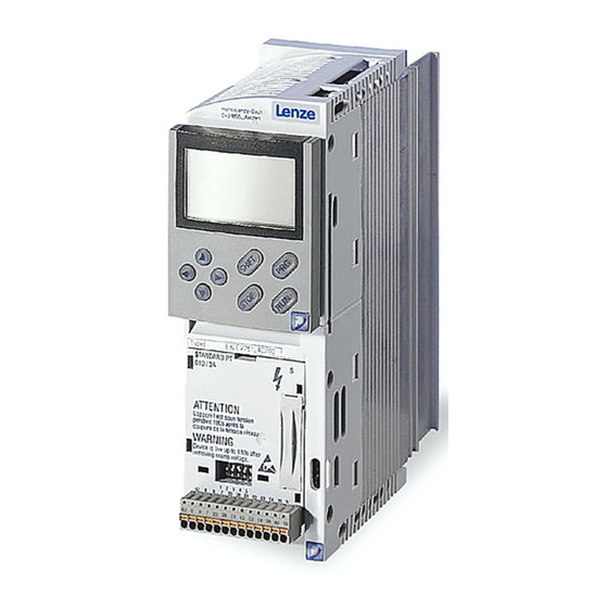
- Page 1 EDK82EVXXX !P2F Information for the operator of the machine/system Global Drive 8200 vector frequency inverter 0.25 ... 90 kW...
- Page 2 8200 vector series installed in your machine/system. All information given in this documentation can be used further without asking Lenze for permission, if you do not change the contents of the information. Note! Current documentation and software updates for Lenze products can be found in the internet in the area ”Downloads”...
-
Page 3: Safety Information
(in conformity with the Low-Voltage Directive 73/23/EEC) General Lenze controllers (frequency inverters, servo inverters, DC controllers) can include live and rotating parts - depending on their type of protection - during operation. Surfaces can be hot. Non-authorized removal of the required cover, inappropriate use, incorrect installation or operation, creates the risk of severe injury to persons or damage to material assets. - Page 4 Safety information Lenze controllers Installation The controllers must be installed and cooled according to the regulations given in the documentation. Ensure proper handling and avoid mechanical stress. Do not bend any components and do not change any insulation distances during transport or handling. Do not touch any electronic components and contacts.
-
Page 5: General Safety And Application Notes For Lenze Motors
Safety information Lenze low-voltage machinery General safety and application notes for Lenze motors (in conformity with the Low-Voltage Directive 73/23/EEC) General Low-voltage machines have dangerous, live and rotating parts as well as possibly hot surfaces. All operations serving transport, connection, commissioning and maintenance are to be carried out by skilled, responsible technical personnel (observe EN 50110-1 (VDE 0105-100);... - Page 6 Safety information Lenze low-voltage machinery Electrical connection All operations must only be carried out by qualified and skilled personnel when the low-voltage machine is at standstill and when the machine is de-energized and protected against unintentional restart. This also applies to auxiliary circuits (e.g. brake, encoder, separate fan).
-
Page 7: Residual Hazards
Safety information Residual hazards, Layout of the safety instructions Residual hazards Protection of persons Before working on the controller check that no voltage is applied to the power terminals, the relay output and the pins of the FIF interface, – because the power terminals U, V, W, +UG, -UG, BR1 and BR2 remain live for at least 3 minutes after mains switch-off. -
Page 8: Signal Word
Safety information Residual hazards, Layout of the safety instructions Layout of safety notes All safety information given in these Instructions have got the same layout: Pictograph (indicates the type of danger) Signal word! (indicates the severity of danger) Note (describes the danger and explains how to avoid it) Pictograph Possible consequences if the Signal word... -
Page 9: Parameter Setting
Parameter setting Parameter setting using the keypad Parameter setting Parameter setting with the E82ZBC keypad Description The keypad is available as accessory. A full description of the keypad can be obtained from the Instructions included in the keypad delivery. Plugging in the keypad It is possible to plug in the keypad onto the AIF interface or remove it during operation. -
Page 10: Display Elements And Function Keys
Bargraph display Value set under C0004 in % Display range: - 180 % ... + 180 % (every bar = 20 %) (Lenze setting: Controller load C0056) Display of parameter set In the mode Display of the parameter set activated via digital signal... -
Page 11: Changing And Saving Parameters
Result Action Connect keypad Function is activated. The first code in the user menu will be displayed (C0517/1, Lenze setting: C0050 = output frequency). xx.xx If necessary change to Change to function bar 2 the menu ”ALL” Select menu ”ALL” (list of all codes) -
Page 12: Menu Structure
For easy operation the codes are divided in two groups: The menu user – is active after every mains switching or keypad attachment during operation. – contains all codes for a standard application with linear V/f characteristic control (Lenze setting). – can be modified as required under C0517. - Page 13 Parameter setting Parameter setting using the keypad Change between the menus u u u u S S S S E E E E r r r r and A A A A L L L L L L L L USEr Œ...
-
Page 14: Troubleshooting And Fault Elimination
DC brake active via terminal error LP1 Unacceptable drive response various Vector control optimisation with vector control Torque dip in the field various Contact Lenze weakening range Stalling of the motor when operating in the field weakening range EDK82EVXXX EN 2.0... - Page 15 Troubleshooting and fault elimination Error messages Operating status green Controller enabled Mains switched on and automatic start inhibited slowly blinking Controller inhibited fast blinking Motor parameter identification fast blinking Undervoltage or overvoltage slowly blinking Error active, check under C0161 f k i h 01 61 ...
- Page 16 (C0410/13, C0410/14) must be combined Faulty parameter setting of parameter set with the same source changeover For operation with module in FIF: Contact Lenze Internal fault • Function module system bus CAN controller sets ”Warning” or ”BUS OFF” Check whether bus terminator available •...
- Page 17 It is absolutely necessary to repeat the data transfer or Faulty parameter transfer when All parameter sets are defective using the keypad load the Lenze setting before enabling the controller. Wrong PAR1 transfer when PAR1 is defective. using the keypad.
- Page 18 Troubleshooting and fault elimination Error messages Keypad Error Cause Remedy Faulty auto-TRIP reset More than 8 fault messages in 10 minutes Depends on the error message Wire breakage analog input 1 Current at analog input < 4 mA at setpoint range 4 Close circuit at analog input ...
Need help?
Do you have a question about the Global Drive 8200 Vector and is the answer not in the manual?
Questions and answers