Table of Contents
Advertisement
Advertisement
Table of Contents

Related Manuals for Lenze DISCO GST Series


Summary of Contents for Lenze DISCO GST Series
- Page 1 BA 11.5032−EN .=<Q Operating Instructions Gearbox DISCO−Variable speed drive...
-
Page 2: Disco Variable Speed Drive Size
Product key LLL − LL LLL DISCO variable speed drive with rear−mounted gearbox − Lengend for the product key Gearbox type Helical gearbox Helical−bevel gearbox Helical−worm gearbox Gearbox size Number of stages Disco variable speed drive Output design Solid shaft Hollow shaft Hollow shaft with shrink disk Foot mounting, with centring... - Page 3 7 L 0 0 0. L DISCO variable speed drive without rear−mounted gearbox Lengend for the product key Product group Product family with motor with free drive shaft DISCO size Free output shaft without motor no data Standard BA 11.5032−EN...
- Page 4 Nameplate DISCO variable speed drive without rear−mounted gearbox GT−DISCO−002.iso Pos. Contents Production location / Name of product Gearbox type Order number Rated speed:drive | output Year of manufacture/ week of manufacture Rated torque Material number Power DISCO variable speed drive with rear−mounted gearbox DISCO nameplate Nameplate of rear−mounted gearbox GT−DISCO−001.iso...
- Page 5 Document history Material number Version Description 410700 09/1999 TD09 Completely revised 483298 12/2003 TD09 Revised description of the mounting position and position of the system blocks 13251318 10/2007 TD09 New nameplate: Compact unit and DISCO version Table of oil grades and new representation of the positions of ventilation, oil filler plug and oil drain plug .=<Q 12/2008...
- Page 6 Mounting position (A−F) and position of system modules (1−6) DISCO variable speed drive with helical gearbox GSTLL − 1D VDR (foot on variable speed drive) Terminal box: 2, 3, 4, 5 Spindle housing: 2, 3, 4, 5 Handwheel/adjusting device: 2, 3, 4, 5 BA 11.5032−EN 3.0...
- Page 7 GSTLL − LD Terminal box: 2, 3, 4, 5 Spindle housing: 2, 3, 4, 5 Handwheel/adjusting device: 2, 3, 4, 5 BA 11.5032−EN...
- Page 8 DISCO variable speed drive with helical−bevel gearbox and helical−worm gearbox GKSLL − LD / GSSLL − LD Solid shaft: 2, 3, 8 (3+5) Hollow shaft: 0 Hollow shaft with shrink disc: 3, 5 Flange: 2, 3, 8 (3+5) Without flange: 0 Terminal box: 2, 3, 4, 5 Spindle housing: 2, 3, 4, 5 Handwheel/adjusting device: 2, 3, 4, 5...
- Page 9 DISCO variable speed drive without rear−mounted gearbox 11.7L0 Terminal box: 2, 3, 4, 5 Handwheel/adjusting device: 2, 3, 4, 5 BA 11.5032−EN...
-
Page 10: Table Of Contents
............Lenze drive systems . - Page 11 Contents Troubleshooting and fault elimination ........Disposal .
-
Page 12: Preface And General Information
After receipt of the supply, check immediately whether it corresponds with the ƒ accompanying papers. Lenze does not grant any warranty for subsequent claims. Claim for – visible transport damages immediately to the forwarder. -
Page 13: Lenze Drive Systems
– improper working on and with the drive system, – operating faults, – disregarding the Operating Instructions. Warranty Conditions of warranty: see terms of sale and delivery of Lenze Drive Systems ƒ GmbH. Warranty claims must be made to Lenze immediately after detecting the deficiency ƒ... -
Page 14: Safety Instructions
Be sure to take appropriate measures in the case of drive system failure so that no ƒ material damage occurs. Operate the drive system only when it is in a proper state. ƒ Retrofittings, modifications, or redesigns of the drive system are basically ƒ prohibited. Lenze must be contacted in all cases. BA 11.5032−EN 3.0... -
Page 15: Definition Of Notes Used
Safety instructions Definition of notes used Definition of notes used The following pictographs and signal words are used in this documentation to indicate dangers and important information: Safety instructions Structure of safety instructions: Danger! (characterises the type and severity of danger) Note (describes the danger and gives information about how to prevent dangerous situations) -
Page 16: Technical Data
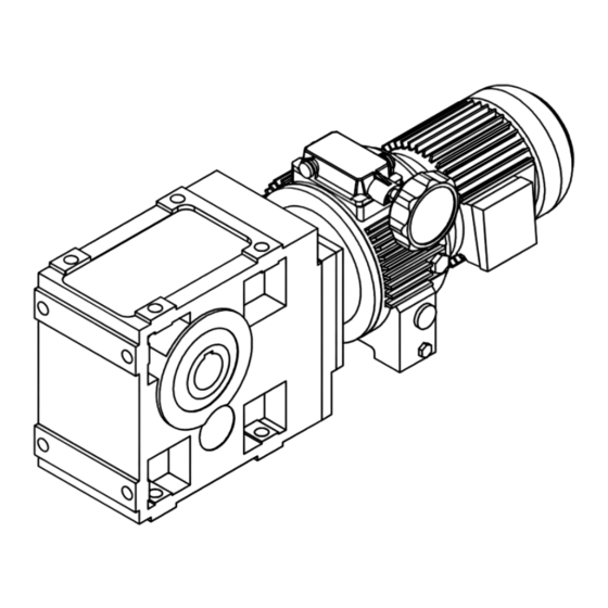
Technical data Product features Technical data The most important technical data are provided on the nameplate (layout and ƒ contents ^ page 4). The product catalogues contain further technical data. ƒ Product features GT−DISCO−005.iso Fig. 1 Layout of the DISCO variable speed drive Pinion shaft Clutch thrust collar Left inner sun... - Page 17 Technical data Product features multi−stage helical, conical or worm gearboxes, can be used to adjust output speed to the requirements of the application. Stop! The DISCO must only be changed to a fasterspeed while it is running! Otherwise, the DISCO could be damaged! Changing to a slowerspeed is allowed while the DISCO is standing still.
-
Page 18: Transport Weights
Technical data Transport weights Transport weights DISCO with GST helical gearbox Gearbox size Drive size 071−1L 02 071−3L 03 080−3L 04 090−3L 05 100−32 06 112−22 07 132−12 18 132−22 08 GST 04 < 18 GST 05 < 25 < 32 <... -
Page 19: Operating Conditions
Technical data Operating conditions Temperatures Operating conditions 3.3.1 Temperatures DISCO: permissible ambient temperature −15 bis +40°C ƒ Rear−mounted gearbox (see Operating Instructions for the gearbox) ƒ Motor (see temperature class for the motor) ƒ The operating temperature is determined by the power loss, the ambient temperature and the cooling system! 3.3.2 Ambient conditions... -
Page 20: Mechanical Installation
Mechanical installation Storage Mechanical installation Danger! Only transport the drive with transport equipment or hoists which are suitable for this load (see transport weights, chapter 3.2). Ensure a safe fixing. Avoid shocks! The motors attached to the gearbox are partially equipped with eyebolts. These are exclusively determined for motor/gearbox mounting and dismounting and must not be used for the complete geared motor! Storage... -
Page 21: Electrical Installation
Electrical installation Electrical adjusting device Electrical installation Danger! Electrical connections must only be carried out by skilled personnel! Danger! Always earth the drive! If it is not possible to earth it via attached items (e.g. the motor) then the gearbox must be earthed! Connection of main motor To connect the motor correctly, you must follow: the notes in the terminal box of the motor... - Page 22 Electrical installation Electrical adjusting device Operational check 4. The adjustment motor and actuator must stop. 5. If the actuator and adjustment motor do not stop, reverse the polarity of the adjustment motor. Adjustment motor in position 3 / limit−switch box in position 5 1.
-
Page 23: Commissioning And Operation
– leakages, – loose fixing elements, – the condition of the electrical cables. If any interference should occur, proceed according to the troubleshooting list in ƒ chapter 8. If the interference cannot be eliminated, please contact the Lenze Service. BA 11.5032−EN... -
Page 24: Maintenance
Maintenance Oil filling quantities for DISCO gearboxes Maintenance The DISCO drives are supplied with oil filling. Note! Lubricating instructions for rear−mounted gearboxes, see Operating ƒ Instructions of the gearbox. We recommend to check the oil level regularly! ƒ If you use an oil not listed in Tab. 2, we recommend lubricants with the ƒ... -
Page 25: Oil Grades For Disco Variable Speed Drives
Maintenance Oil filling quantities for DISCO gearboxes Oil grades for DISCO variable speed drives 7.1.1 Oil grades for DISCO variable speed drives Manufacturer Oil types DISCO lifetime oil Shell Tegula V 32 Astron HLP 32 / Pentran 32 Shell LAMORA HLP 32 RENOLIN MR 10 VG 32 / RENOFLUID TF 1500 Degol GB 32 OSO 32 / BLASIA 32... -
Page 26: Breather Position, Oil Filling Screw And Drain Plug
Maintenance Oil filling quantities for DISCO gearboxes Breather position, oil filling screw and drain plug 7.1.2 Breather position, oil filling screw and drain plug GT−DISCO−007.cdr Oil filling for gearboxes without ventilation Ventilation / oil filler plug Oil drain plug Oil control plug Facing the housing In case of a position of the handle different from the shown one, the positions are facing the housing respectively BA 11.5032−EN 3.0... -
Page 27: Maintenance Intervals
4. Fit the oil filler plug. 5. Dispose of the used oil according to current regulations. 7.3.2 Spare parts list You find the spare parts list in the10appendix Repair Lenze recommends that repairs are carried out by the Lenze Service. BA 11.5032−EN... -
Page 28: Troubleshooting And Fault Elimination
Check drive−machine assignment Motor runs, gearbox does not Coupling components are missing or Check mounting defective Gearbox is defective Inform Lenze Service Unusual running noise Overload Reduce load Check drive−machine assignment Damage to the gearbox or motor Inform Lenze Service... -
Page 29: Disposal
Disposal Disposal Protect the environment! Valuable materials can be recycled. What? Where? Transport material Pallets Return to the manufacturer or forwarder Packaging material Cardboard box to waste paper Plastics to plastics recycling or residual waste Reuse or dispose of wood wool Lubricants Oil, grease Dispose according to current... -
Page 30: Appendix
Appendix Spare−parts list DISCO variable speed drive size 02 Appendix 10.1 Spare−parts list 10.1.1 DISCO variable speed drive size 02 1.07 1.03 4471 4401 4420 4410 1.08 4424 4423 4421 4425 BA 11.5032−EN 3.0... - Page 31 Appendix Pos. Name Pos. Name Pos. Name 0.25 Seal 3.19 Socket 4.37 Dowel pin 0.26 Seal 3.26 Socket 4.38 Dowel pin 0.28 Hexagon head cap screw 3.27 Pressure spring 4.39 Set screw 0.29 Locking washer for sizes 02−03 3.28 Deep−groove ball bearing 4.40 Set screw Spring washer for sizes 04−07...
- Page 32 Appendix DISCO variable speed drive size 03 10.1.2 DISCO variable speed drive size 03 4471 4401 4410 1.08 4422 4423 4420 4425 4421 BA 11.5032−EN 3.0...
- Page 33 Appendix Pos. Name Pos. Name Pos. Name 0.25 Seal 3.09 Pinion cage 4.28 Circlip 0.26 Seal 3.10 Slide block 4.29 Locking ring 0.28 Hexagon head cap screw 3.11 Socket 4.31 Shim ring 0.29 Locking washer for sizes 02−03 3.12 Washer 4.32 Seeger ring Spring washer for sizes 04−07...
-
Page 34: Disco Variable Speed Drive Size 04−07
Appendix DISCO variable speed drive size 04−07 10.1.3 DISCO variable speed drive size 04−07 4471 4401 4421 4410 1.08 4420 4425 4423 4422 BA 11.5032−EN 3.0... - Page 35 Appendix Pos. Name Pos. Name Pos. Name 0.25 Seal 3.09 Pinion cage 4.28 Circlip 0.26 Seal 3.10 Slide block 4.29 Locking ring 0.28 Hexagon head cap screw 3.11 Socket 4.31 Shim ring 0.29 Locking washer for sizes 02−03 3.12 Washer 4.32 Seeger ring Spring washer for sizes 04−07...
-
Page 36: Disco Variable Speed Drive Size 08−18
Appendix DISCO variable speed drive size 08−18 10.1.4 DISCO variable speed drive size 08−18 4401 4471 4421 4410 4420 1.08 4422 4423 4424 4425 BA 11.5032−EN 3.0... - Page 37 Appendix Pos. Name Pos. Name Pos. Name 0.25 Seal 3.01 Cover 4401 Flange 0.26 Seal 3.03 Flange 4410 Shaft 0.28 Hexagon head cap screw 3.05 Shaft 4420 Deep−groove ball bearing 0.29 Locking washer for sizes 02−03 3.08 4421 Shaft sealing ring Spring washer for sizes 04−07 3.09 Pinion cage...
-
Page 38: Speed Adjustment Mechanism, Size 02−07
Appendix Speed adjustment mechanism, size 02−07 10.1.5 Speed adjustment mechanism, size 02−07 BA 11.5032−EN 3.0... - Page 39 Appendix Pos. Name Pos. Name 4.00 Spindle housing assembly 5.00 Limit−switch assembly 4.01 Spindle housing 5.01 Housing 4.02 Housing 5.02 Housing 4.03 Spindle 5.03 Actuator 4.04 Guide part 5.04 Board assembly 4.05 Shaft 5.05 Plate 4.06 Ball headed pin 5.06 Microswitch 4.08 Socket...
-
Page 40: Speed Adjustment Mechanisms, Size 08−18
Appendix Speed adjustment mechanisms, size 08−18 10.1.6 Speed adjustment mechanisms, size 08−18 BA 11.5032−EN 3.0... - Page 41 Appendix Pos. Name Pos. Name 1.01 Housing 4.53 Spring washer 1.02 Thrust collar 4.55 1.03 Foot 4.56 Bell housing 1.04 Set screw 4.57 Handle 1.05 Seal−Lock hexagon nut 4.58 Hexagon head cap screw 1.06 Dowel pin 5.00 Limit−switch assembly 1.07 Cheese head screw 5.01 Housing...
- Page 42 Notes BA 11.5032−EN 3.0...
- Page 43 Notes BA 11.5032−EN...
- Page 44 Lenze Drives GmbH BA 11.5032−EN 3.0 12/2008 Postfach 10 13 52 © 2008 D−31763 Hameln TD09 Germany +49 (0)51 54 / 82−0 Service 00 80 00 / 24 4 68 77 (24 h helpline) Ê Service +49 (0)51 54 / 82−28 00 E−Mail...
Need help?
Do you have a question about the DISCO GST Series and is the answer not in the manual?
Questions and answers