Table of Contents
Advertisement
Quick Links
Advertisement
Table of Contents

Related Manuals for Pilz PSEN opII3F Series


Summary of Contents for Pilz PSEN opII3F Series
- Page 1 PSEN opII3F Series PSEN sensor technology Operating Manual 1003504-EN-01...
- Page 2 Preface This document is a translation of the original document. All rights to this documentation are reserved by Pilz GmbH & Co. KG. Copies may be made for internal purposes. Suggestions and comments for improving this documentation will be gratefully received.
-
Page 3: Table Of Contents
Attach the safety light grid to the installation surface Orientation General guidelines Safety light grid alignment Wiring General guidelines Connector pin assignment Earthing the safety light grid Commissioning System connection Checking the safety light grid Operating Manual PSEN opII3F Series 1003504-EN-01... - Page 4 Technical details Order no. 632046-632048 Technical details Order no. 632049-632051 Safety characteristic data Order reference Order reference for safety light grids Order reference for accessories Order reference: Component parts Appendix Check list EC declaration of conformity Operating Manual PSEN opII3F Series 1003504-EN-01...
-
Page 5: Introduction
PSEN opII3F Series Introduction Validity of documentation This documentation is valid for the product PSEN opII3F Series. It is valid until new docu- mentation is published. This operating manual explains the function and operation, describes the installation and provides guidelines on how to connect the product. -
Page 6: Overview
Overview Safety light grids in the PSEN opII3F Series constitute electrosensitive protective equip- ment (ESPE type: 3) in accordance with DIN EN 61496-1 for work areas in which ma- chines, robots, and automated systems could endanger the physical integrity of operators. - Page 7 PSEN opII3F Series – Protected field heights of 750-1200 mm, including: 1 PSEN opII Adv Bracket Kit-3 (=3 clamping units per transmitter and receiver) – Protected field heights of 1350-1800 mm, including: 2 PSEN opII Adv Bracket Kit-2 (=4 clamping units per transmitter and receiver) Operating Manual PSEN opII3F Series 1003504-EN-01...
-
Page 8: Unit View
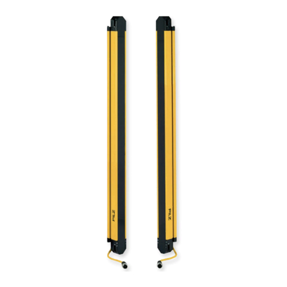
Fig.: Front view of the safety light grid transmitter and receiver, protected field height 300-1800 mm with connection cable Legende [1] Protected field height [2] Effective protected field height [3] Tinted front panel [4] LEDs for status information Operating Manual PSEN opII3F Series 1003504-EN-01... - Page 9 Fig.: Front view of the safety light grid transmitter and receiver, protected field height 150 mm with connection cable Legende [1] Protected field height [2] Effective protected field height [3] Tinted front panel [4] LEDs for status information [5] Connection cable, M12 connector [6] Optical centre axis Operating Manual PSEN opII3F Series 1003504-EN-01...
-
Page 10: Scope
Holder for connecting the transmitter/re- ceiver end caps to the flexible bracket Tightening screw M3x33.4 oval-head screw, self-tapping Clamping screw with ISO 4762 M4x10 8.8 cylinder screw with Mounting screw ISO 4762 M6x20 8.8 cylinder screw with washer Operating Manual PSEN opII3F Series 1003504-EN-01... -
Page 11: Safety
PSEN opII3F Series Safety Intended use Safety light grids of the PSEN opII3F Series are electrosensitive protective equipment of the 3. They are used to protect personnel and systems. The safety light grids are designed securing hazardous areas within buildings and securing access within buildings with a resolution of 14 mm. -
Page 12: Safety Regulations
In safety-related applications, please comply with the mission time T in the safety-re- lated characteristic data. When decommissioning, please comply with local regulations regarding the disposal of electronic devices (e.g. Electrical and Electronic Equipment Act). Operating Manual PSEN opII3F Series 1003504-EN-01... -
Page 13: Function Description
[ of the safety light grid. The safety light grid of the PSEN opII3F Series offers the following functions: automatic start automatic restart Operation of 2 safety light grids that are parallel to one another and are installed with... - Page 14 Check is begun to determine whether the protected field is clear and whether there are errors Response time required for the OSSDs to switch to the OFF state (see Tech- nical details [ 42]) Minimum time that the OSSDs remain in the OFF state: 80 ms Operating Manual PSEN opII3F Series 1003504-EN-01...
-
Page 15: Project Configuration
Machine's stopping time in seconds The time required for the machine to stop after the signal at the OSSD output changes Additional distance of 0 mm for safety light grids with finger protection Operating Manual PSEN opII3F Series 1003504-EN-01... -
Page 16: Resolution
The transmitters and receivers of two different safety light grids must not be synchron- ised. Avoid strong electromagnetic interference when operating the safety light grid. When operating the safety light grid, avoid the development of smoke, mist, or dust that would reduce the grid’s operating range. Operating Manual PSEN opII3F Series 1003504-EN-01... -
Page 17: Distance From Reflective Surfaces
This means that there must be a certain minimum distance between the safety light grid and reflective surfaces. Fig.: Interference with the function of the safety light grid due to reflective surfaces – top view Operating Manual PSEN opII3F Series 1003504-EN-01... - Page 18 The minimum distance D depends on two factors: Working distance between transmitter and receiver the maximum opening angle [ of the light beams emitted by the safety light grid 5° = ± 2.5° in relation to the optical axis Operating Manual PSEN opII3F Series 1003504-EN-01...
- Page 19 For a working distance of 3 m or more: D = working distance in m x tan ⍺ 0,35 0,174 0,131 Fig.: Relationship between minimum distance and working distance Legende [1] Working distance in m [2] Minimum distance D to reflective surfaces in m Operating Manual PSEN opII3F Series 1003504-EN-01...
-
Page 20: Minimum Distance Between Parallel, Aligned Safety Light Grids
[5] Minimum distance of 2 x D between two safety light grids that are aligned [6] Working distance [7] Minimum distance D, dependent on the working distance [8] Working distance (= 3 m) with constant minimum distance D = 0.131 m Operating Manual PSEN opII3F Series 1003504-EN-01... -
Page 21: Installation Of Several Adjacent Safety Light Grids
Please consider this reduc- tion when positioning the safety light grid. You should not use more than two mirrors per device. Any dust or dirt on the mirror’s reflective surface will drastically reduce the operating range. Operating Manual PSEN opII3F Series 1003504-EN-01... -
Page 22: Dead Zones
Use of the standard installation kit results in a dead zone of 15.4 mm on both sides of the safety light grid. If you want to use the safety light grid without dead zones, use the PSEN opII Adv Bracket Kit for safety light grid installation (see Dead-zone-free installation [ 6]). Operating Manual PSEN opII3F Series 1003504-EN-01... - Page 23 Fig.: Placement of the dead zones in vertical safety light grid installation Legende [1] Last light beam (wiring side) [2] Last light beam (cable side) [3] Wiring-side dead zone [4] Cable-side dead zone Operating Manual PSEN opII3F Series 1003504-EN-01...
-
Page 24: Installation And Orientation
(see Technical details [ 42]). The installation surface must be at least as wide as the standard installation kit The installation surface may have a flatness imperfection of no more than 1.5 mm. Operating Manual PSEN opII3F Series 1003504-EN-01... -
Page 25: Attach The Safety Light Grid To The Installation Surface
Feed the cable [2] through the opening in the holder. Ensure that the holder is flush with the end cap (see diagram). Attach the holder to the end cap with the tightening screws included in delivery. [1] Torque setting 0,7 Nm Operating Manual PSEN opII3F Series 1003504-EN-01... - Page 26 [1]: The angle [4] of the flexible bracket [3] on the holder [2] may not be more than 2°. The flexible bracket [3] must be seated on one side of the holder [2]. Operating Manual PSEN opII3F Series 1003504-EN-01...
- Page 27 Ensure that the transmitters and receivers are properly installed in a suitable place. Ensure that the transmitters and receivers are posi- tioned at the same height and parallel to one another. Operating Manual PSEN opII3F Series 1003504-EN-01...
-
Page 28: Orientation
[2] Horizontal: by horizontal shifting of position in the elongated holes in the top and bot- tom flexible brackets [3] The axis orientation can be changed by rotating the flexible bracket right or left Pilz recommends that modifications to the orientation of the transmitter/receiver be made in the following sequence: 1. Vertical modification 2. -
Page 29: Safety Light Grid Alignment
Tighten the clamping screws [1] and the nuts [2] on the flexible bracket to a torque of 1,1 Nm. Tighten the brackets’ mounting screws [3] on the installation surface to a torque of 3 Operating Manual PSEN opII3F Series 1003504-EN-01... -
Page 30: Wiring
The transmitters and receivers must be electrically isolated from the ma- chine/system. The use of the flexible bracket (swivel mount) provides this electrical isolation. Connection to PDP67 – Use the order reference of the cable listed (see Accessories, connection to PDP67 [ 54]) Operating Manual PSEN opII3F Series 1003504-EN-01... -
Page 31: Connector Pin Assignment
(such as EN 60204-1, NFPA 79:17-7, NEC: Article 250). Connections should be protected from corrosion. Flexible earthing straps should be used on moving earth parts (e.g. machine parts, gates). Ensure these earthing straps are as short and wide as possible. Operating Manual PSEN opII3F Series 1003504-EN-01... -
Page 32: Commissioning
2-channel with feasibility monitoring OSSD signals are evaluated A test pulse lasting no longer than 300 µs is bridged Suitable Pilz evaluation devices are, for example: PNOZelog for monitoring safety light grids PNOZsigma for monitoring safety light grids PNOZ X for monitoring safety light grids... -
Page 33: Checking The Safety Light Grid
Fig.: Dual-channel connection of the safety light grid to the input circuit of an evaluation device CAUTION! When considering the examples, please note that Pilz accepts no respons- ibility for the specific application. In particular, they may not be used without testing and approval. - Page 34 In the centre of the protected field 2. Place the test rod at rest in a position in the protected field that is considered critical for the safety assessment results Legend [1] Test rod Operating Manual PSEN opII3F Series 1003504-EN-01...
-
Page 35: Operation
The safety light grid’s operating status is indicated with LEDs in the end caps of the con- nection side of the receiver and on the transmitter. Device status Reception quality: III: best quality OSSD status (protected field LED) I: worst quality LED indicator on the receiver Operating Manual PSEN opII3F Series 1003504-EN-01... -
Page 36: Status Information
An error has occurred. Perform a safety light grid restart [ 38]. Interfering light warning Warns of the OSSDs’ change to green green green green green the OFF state due to incident inter- fering light. Operating Manual PSEN opII3F Series 1003504-EN-01... - Page 37 [ 38]. Indicators on the transmitter Meaning Safety light grid is started green green green Safety light grid in operation green green An error has occurred. Perform a safety light grid restart [ 38]. Operating Manual PSEN opII3F Series 1003504-EN-01...
-
Page 38: Safety Light Grid Restart
Regular checks can bring to light changes to the plant/machine, safeguards and ambient conditions. Regular check Pilz recommends that the safety light grid be checked every six months. Check the safety light grid’s front panel. – Scratched front panel: Replace the safety light grid. -
Page 39: Check After Plant/Machine Modification
Moist cotton cloths should be used for cleaning. Avoid using Alcohol, Solvents, Cloths made of wool, Cloths made of synthetic material. Clean the lens covers during the regular check of the safety light grid [ 38]. Operating Manual PSEN opII3F Series 1003504-EN-01... -
Page 40: Dimensions
Fig.: Front view of the safety light grid transmitter, protected field height 150 mm with connection cable Legende [1] Total length of transmitter (without cable) [2] Effective protected field height [3] Protected field height (see Technical details [ 42]) Operating Manual PSEN opII3F Series 1003504-EN-01... - Page 41 Fig.: Relationship between the effective protected field height and the safety light grid dimensions (schematic representation) Legende [1] Resolution [2] Last light beams on the connection and wiring sides [3] Protected field height [4] Effective protected field height [5] Transmitter [6] Receiver Operating Manual PSEN opII3F Series 1003504-EN-01...
-
Page 42: Technical Details Order No. 632040-632042
Times 632040 632041 632042 Test pulse duration, safety outputs 300 µs 300 µs 300 µs Supply interruption before de-energisation 600 µs 600 µs 600 µs Response time t1 14 ms 14 ms 15 ms Operating Manual PSEN opII3F Series 1003504-EN-01... - Page 43 M12, 5-pin male con- M12, 5-pin male con- nector nector nector Transmitter M12, 5-pin male con- M12, 5-pin male con- M12, 5-pin male con- nector nector nector Max. cable length 50 m 50 m 50 m Operating Manual PSEN opII3F Series 1003504-EN-01...
-
Page 44: Technical Details Order No. 632043-632045
-25 %/+20 % -25 %/+20 % Residual ripple DC Max. power consumption receiver 12 W 12 W 12 W Max. power consumption transmitter 7,2 W 7,2 W 7,2 W Max. inductive load per output Operating Manual PSEN opII3F Series 1003504-EN-01... - Page 45 EN 61496-1 Vibration In accordance with the standard EN 60068-2-6 EN 60068-2-6 EN 60068-2-6 Frequency 10 - 150 Hz 10 - 150 Hz 10 - 150 Hz Amplitude 0,75 mm 0,75 mm 0,75 mm Operating Manual PSEN opII3F Series 1003504-EN-01...
- Page 46 754 mm 904 mm Width 35 mm 35 mm 35 mm Depth 40 mm 40 mm 40 mm Weight 1.850 g 2.263 g 2.675 g Where standards are undated, the 2015-12 latest editions shall apply. Operating Manual PSEN opII3F Series 1003504-EN-01...
-
Page 47: Technical Details Order No. 632046-632048
Times 632046 632047 632048 Test pulse duration, safety outputs 300 µs 300 µs 300 µs Supply interruption before de-energisation 600 µs 600 µs 600 µs Response time t1 17 ms 18 ms 19 ms Operating Manual PSEN opII3F Series 1003504-EN-01... - Page 48 M12, 5-pin male con- M12, 5-pin male con- nector nector nector Transmitter M12, 5-pin male con- M12, 5-pin male con- M12, 5-pin male con- nector nector nector Max. cable length 50 m 50 m 50 m Operating Manual PSEN opII3F Series 1003504-EN-01...
-
Page 49: Technical Details Order No. 632049-632051
-25 %/+20 % -25 %/+20 % Residual ripple DC Max. power consumption receiver 12 W 12 W 12 W Max. power consumption transmitter 7,2 W 7,2 W 7,2 W Max. inductive load per output Operating Manual PSEN opII3F Series 1003504-EN-01... - Page 50 EN 61496-1 Vibration In accordance with the standard EN 60068-2-6 EN 60068-2-6 EN 60068-2-6 Frequency 10 - 150 Hz 10 - 150 Hz 10 - 150 Hz Amplitude 0,75 mm 0,75 mm 0,75 mm Operating Manual PSEN opII3F Series 1003504-EN-01...
- Page 51 1.654 mm 1.804 mm Width 35 mm 35 mm 35 mm Depth 40 mm 40 mm 40 mm Weight 4.325 g 4.738 g 5.150 g Where standards are undated, the 2015-12 latest editions shall apply. Operating Manual PSEN opII3F Series 1003504-EN-01...
-
Page 52: Safety Characteristic Data
PSEN opII3F- Safety light grid for finger protection, protected field height of 750 mm 632 044 S-14-075 PSEN opII3F- Safety light grid for finger protection, protected field height of 900 mm 632 045 S-14-090 Operating Manual PSEN opII3F Series 1003504-EN-01... -
Page 53: Order Reference For Accessories
750 mm and 1200 mm (inclusive) Laser orientation aid Product type Features Order No. PSEN opII laser Laser orientation aid for safety light grids from the PSEN opII series 632 014 pointer Operating Manual PSEN opII3F Series 1003504-EN-01... - Page 54 Length Order No. PSEN op cable unshielded, straight, Open cable 630 310 M12-5sf M12, 5-pin, socket 630 311 10 m 630 312 20 m 630 298 30 m 630 297 50 m 630 364 Operating Manual PSEN opII3F Series 1003504-EN-01...
-
Page 55: Order Reference: Component Parts
PSEN opII3F- For safety light grid for finger protection, protected field height of 450 632342 s-14-045 receiver PSEN opII3F- For safety light grid for finger protection, protected field height of 600 632343 s-14-060 receiver Operating Manual PSEN opII3F Series 1003504-EN-01... -
Page 56: Appendix
INFORMATION Commissioning, recommissioning and regular inspection may only be car- ried out by qualified personnel. We recommend that you keep the completed check list and store it with the machine docu- mentation for reference. Operating Manual PSEN opII3F Series 1003504-EN-01... - Page 57 (such as the glass panel). Are all the mechanical connections on the safety light grid attached correctly? Are all the electrical connections to the safety light grid wired correctly? Operating Manual PSEN opII3F Series 1003504-EN-01...
-
Page 58: Ec Declaration Of Conformity
European Parliament and of the Council. The complete EC Declaration of Conformity is available on the Internet at www.pilz.com/downloads. Representative: Norbert Fröhlich, Pilz GmbH & Co. KG, Felix-Wankel-Str. 2, 73760 Ost- fildern, Germany Operating Manual PSEN opII3F Series... - Page 59 Back cover Support Technical support is available from Pilz round the clock. Americas Australia Scandinavia Brazil +61 3 95446300 +45 74436332 +55 11 97569-2804 Spain Canada Europe +34 938497433 +1 888-315-PILZ (315-7459) Austria Switzerland Mexico +43 1 7986263-0 +41 62 88979-30...
Need help?
Do you have a question about the PSEN opII3F Series and is the answer not in the manual?
Questions and answers