Table of Contents
Advertisement
Quick Links
Power VI-GL
™
Assembly & Use Instructions
For 220v Models
FULL
2
YEAR
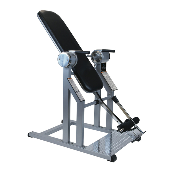
* Specifications may vary from this image and
are subject to change without notice.
The Power VI-GL is shown here.
Your actual model may vary.
To download and print Teeter's Power VI-GL instructions, visit the product support page at teeter.com.
EN
Advertisement
Table of Contents

Related Manuals for Teeter Power VI-GL


Summary of Contents for Teeter Power VI-GL
- Page 1 * Specifications may vary from this image and are subject to change without notice. The Power VI-GL is shown here. Your actual model may vary. To download and print Teeter’s Power VI-GL instructions, visit the product support page at teeter.com.
-
Page 2: Table Of Contents
ATTENTION FACILITY USE PERSONNEL The Teeter Power VI-GL Inversion Table is commercial- grade equipment intended for use in fitness facilities. In this manual, you will find important information how to assemble, maintain and use the inversion table. The Power VI-GL inversion Table provides progressive decompression to help relieve back pain by releasing tension and stress, rejuvenating discs, and reducing nerve pressure. -
Page 3: General Warnings
• If the equipment is damaged or inoperable, unplug and keep out of use until repair. DO NOT attempt to repair the equipment - there are no user serviceable parts and is not field serviceable. Contact Teeter Customer Support for service. ALWAYS dispose of per local regulations. -
Page 4: Important Safety Instructions
VOLTAGE INFORMATION • The power requirement for the Teeter Power VI Inversion Table include a grounded, dedicated circuit with a nominal voltage of 220 VAC at 50 Hz. Voltage requirements are also located on the serial number decal on the inversion table. -
Page 5: Proper Training Of Facility Staff
Important Safety Instructions PROPER TRAINING OF FACILITY STAFF • Facilities are responsible for evaluating their own clientele to determine who should and should not use the equipment. It is also the facility's responsibility to review the health contraindications, safety, and user instructions with all users prior to allowing them access to the equipment. -
Page 6: Items For Assembly
Items for Assembly Items not shown to scale. Hardware drawings located on the insert inside each Hardware Kit. ITEM NO. ITEM NAME Table Frame & Base Assembly P12002 Base Platform P12001 Frame pre-assembled Table Bed Main Shaft Assembly P19521 Main Shaft with Ankle Lock System P11003 Locking Knobs (2) Handle Assembly... -
Page 7: Understanding Your Inversion Table
Identifying Parts & Components Before reading further, study the drawing below to familiarize yourself with the important components of the Power VI-GL Inversion Table. Identifying Parts and Components Table Bed Ankle Lock System Rotation Control Button Foot Platform Handles Main Shaft... -
Page 8: Safety Warning Labels & Product Specifications
Important: Please review all labels and supporting materials before using your inversion table. This drawing indicates the locations of the warning labels and placards found on your product. If a label or placard is missing, illegible or is removed, contact Teeter Customer Service to request a complimentary replacement. ATTENTION If a power failure occurs, remain calm. -
Page 9: Assembly Steps
STEP 1 Assemble Table Frame to the Base NOTE: The Table Bed arrives rotated into the fully inverted position. This FIGURE 1 is the most convenient position from which to begin the assembly process. • Place the Base flat on the floor, with the holes up (Figure 1). The holes in the Base are off-center toward the front. - Page 10 STEP 2 Assemble Main Shaft to the Table Frame • With one of the Locking Knobs in hand, insert the Main Shaft into the FIGURE 3 FIGURE 4 Bed Frame Assembly (Figure 3). • Install the main shaft in the Standard Setting by lining up the first set of holes on the Main Shaft with the back of the Table Bed (Figure 3).
- Page 11 STEP 4 Connect to Power Source • Connect to an appropriate outlet that is properly installed and FIGURE 6 grounded in accordance with all local codes and ordinances. • Rotate the upright using the Rotation Control Button. The movement is indicated by the arrows (Figure 6).
-
Page 12: Prepare To Invert
Prepare to Invert Before Using the Inversion Table FIGURE 7 • Make sure the inversion table rotates smoothly to the fully inverted position and back by pushing the Rotation Control Button (Figure 7). Be sure to check that there is adequate clearance to rotate in front, above and behind you. - Page 13 Prepare to Invert Securing Your Ankles (continued) FIGURE 13 5. Pull the Ankle Lock Handle towards your legs (Figure 13) and release when the Front Foam Rollers & Rear Ankle Cups fit snug, with a close fit against the smallest part of your ankles (Figure 14). Jiggle the Ankle Lock Handle from front to back to make sure it has fully engaged and is locked securely.
-
Page 14: How To Invert
How to Invert • Ensure there is clearance for the Table Bed to rotate without FIGURE 15 contacting other objects or people. • To begin inversion, push the Rotation Control Button in the direction of your head. Release the button at the desired angle of inversion (Figure 16). - Page 15 Under no circumstances shall Teeter, or any other party involved in the sale of this product, have any liability for incidental or consequential damage arising from breach of an express or implied warranty on any Teeter product.
- Page 16 Tel. +49 511 62628630 device will void the TUV Listing. U.S. and Foreign Patents Apply. Teeter and Teeter logo are registered trademarks of Teeter. Specifications subject to change without notice. © COPYRIGHT 2016 Teeter. International Law Prohibits Any Copying. LP2240 0416-6...
Need help?
Do you have a question about the Power VI-GL and is the answer not in the manual?
Questions and answers