
Related Manuals for Amazone AD 3000 Super Classic Line


Summary of Contents for Amazone AD 3000 Super Classic Line
- Page 1 Operating manual Pack top seed drill AD 3000 Super Classic Line Please read and observe this operating manual before initial MG6820 operation of the implement! BAH0107-0 02.20 Keep it in a safe place for future use!
- Page 3 + 49 (0) 5405 50 1-0 E-mail: amazone@amazone.de Spare Parts Order Spare parts lists are freely accessible in the spare parts portal at www.amazone.de. Please send orders to your AMAZONE dealer. Formalities of the operating manual Type: AD 3000 Super Classic Line Document number: MG6820 Compilation date: 02.20...
- Page 4 Foreword Dear Customer, You have chosen one of the quality products from the wide product range of AMAZONEN-WERKE, H. DREYER GmbH & Co. KG. We thank you for your trust in our products. On receiving the implement, check to see if it has been damaged during transport or if parts are missing.
-
Page 5: Table Of Contents
Loading and unloading the implement upon delivery ......35 Product description ................... 36 Components of the AMAZONE seeding combination ............36 Assembly groups of the AD 3000 Super pack top seed drill ..........37 ... - Page 6 Seeding shaft drive........................ 56 Metering ..........................57 5.7.1 Setting values ........................58 5.7.2 Normal and fine seed metering wheel................... 60 5.7.3 Fine seed metering wheel brushes ..................60 5.7.4 Bean seed metering wheel ....................60 ...
- Page 7 7.2.5 Uncoupling the seed drill from KG/KE/KX 00 soil tillage implements with 2-tube system roller frame Tooth packer roller PW 600 Wedge ring roller KW 580 ...... 108 7.2.6 Mounting the seed drill on KG/KE/KX 01 soil tillage implements with 2-tube system ...
- Page 8 8.15 Moving the exact following harrow road safety bar into road transport/parking position ..........................158 8.15.1 Moving the road safety bar into road transport position ............158 8.15.2 Moving the road safety bar into parking position ..............158 ...
- Page 9 AD 3000 Super BAH0107-0 02.20...
-
Page 10: User Information
User information User information The User information section provides information concerning the operating manual. This operating manual is valid for all versions of the implement. Figures serve as a reference and are to be understood as representations of the principle. All of the equipment is described without indicating it as special equipment. -
Page 11: General Safety Instructions
General Safety Instructions General Safety Instructions This section contains important information on safe operation of the implement. Obligations and liability Comply with the instructions in the operating manual Knowledge of the basic safety information and safety regulations is a basic requirement for safe handling and fault-free implement operation. - Page 12 General Safety Instructions Risks in handling the implement The implement has been constructed to the state-of-the art and the recognised rules of safety. However, operating the implement may cause risks and restrictions the health and safety of the user or third persons ...
-
Page 13: Representation Of Safety Symbols
General Safety Instructions Representation of safety symbols Safety instructions are indicated by the triangular safety symbol and the highlighted signal word. The signal word (DANGER, WARNING, CAUTION) describes the severity of the risk, and carries the following meaning: DANGER Indicates an immediate hazard with high risk, which will result in death or serious bodily harm (loss of limbs or long-term harm), if it is not avoided. -
Page 14: Organisational Measures
General Safety Instructions Organisational measures The operator must provide the necessary personal protective equipment as per the information provided by the manufacturer of the crop protection agent to be used, such as: Safety glasses Protective shoes Chemical-resistant overalls ... -
Page 15: User Training
General Safety Instructions User training Only those people who have been trained and instructed may work with/on the implement. The operator must clearly specify the responsibilities of the people charged with operation and maintenance work. People being trained may only work with/on the implement under the supervision of an experienced person. -
Page 16: Safety Measures In Normal Operation
General Safety Instructions Safety measures in normal operation Only operate the implement if all the safety and protection equipment is fully functional. Check the implement at least once a day for visible damage and check the function of the safety and protection equipment. -
Page 17: Spare And Wear Parts And Aids
Immediately replace any implement parts which are not in a perfect state. Use only genuine AMAZONE spare and wear parts or the parts cleared by AMAZONEN-WERKE so that the operating permit retains its validity in accordance with national and international regulations. If you use wear and spare parts from third parties, there is no guarantee that they have been designed and manufactured in such a way as to meet the requirements placed on them. -
Page 18: Warning Symbols On The Implement
Warning symbols on the implement Always keep all the warning symbols of the implement clean and in a legible state! Replace illegible warning symbols. You can request the warning symbols from your AMAZONE dealer using the order number (e.g., MD 075). Structure Warning symbols indicate danger areas on the implement and warn against residual dangers. - Page 19 General Safety Instructions MD 076 Risk of drawing-in/entrapment for hand or arm due to moving force-transmission parts! This hazard can cause extremely serious injuries resulting in the loss of limbs. Never open or remove protective equipment, while the tractor engine is running with the universal joint shaft or hydraulic/electronic system connected.
- Page 20 General Safety Instructions MD 083 Danger of arms being drawn in and/or caught by moving parts involved in the working process! This hazard can cause extremely serious injuries resulting in the loss of limbs. Never open or remove protective devices while the tractor engine is running with the universal joint shaft/hydraulic or electronic systems connected.
- Page 21 General Safety Instructions MD 094 Risk of electric shock or burns from accidentally touching overhead power lines or by coming within the prohibited distance of high voltage overhead power lines. These dangers can cause extremely serious and potentially fatal injuries. Maintain a sufficient distance from electrical overhead cables when swinging any parts of the implement in and out.
- Page 22 General Safety Instructions MD 097 Risk of crushing the entire body when standing in the lifting area of the three-point hitch when the three-point hydraulic system is being operated! Causes serious, potentially fatal injuries anywhere on the body. It is forbidden to stand in the lifting area of the three-point hitch when actuating the three-point hydraulic system.
- Page 23 General Safety Instructions MD 154 Danger of cuts for other road users caused by transport with unguarded, sharp harrow tines of the seed harrow! Causes serious, potentially fatal injuries anywhere on the body. Transportation without a correctly fitted road safety bar is forbidden.
-
Page 24: Position Of Warning Symbols
General Safety Instructions 2.13.1 Position of warning symbols The following figures show the arrangement of the warning symbols on the implement. Fig. 1 Fig. 2 AD 3000 Super BAH0107-0 02.20... -
Page 25: Dangers In Case Of Non-Compliance With The Safety Instructions
General Safety Instructions Fig. 3 Fig. 4 2.14 Dangers in case of non-compliance with the safety instructions Non-compliance with the safety information can pose both a danger to people and to the environment and implement can result in the loss of an claims for damages. In particular, non-compliance with the safety information could pose the following risks: ... -
Page 26: Safety Information For Users
General Safety Instructions 2.16 Safety information for users WARNING Risk of crushing, cutting, being trapped or drawn in, or impact through inadequate roadworthiness and operational safety. Before starting up the implement and the tractor each time, always check their traffic and operational safety. CAUTION Before adjustment, maintenance and repair work ... - Page 27 General Safety Instructions Coupling and uncoupling the implement Only connect and transport the implement with tractors suitable for the task. When coupling implements to the tractor's three-point hydraulic system, the mounting categories of the tractor and the implement must always be compatible. ...
- Page 28 General Safety Instructions Use of the implement Before starting work, make sure that you understand all the equipment and control elements of the implement and their functions. It is too late for this when the implement is already in operation.
- Page 29 General Safety Instructions Implement transportation When using public roads, national road traffic regulations must be observed. Switch off the control terminal before road transport. Before road transport, check that the supply lines are connected correctly the lighting system for damage, function and cleanliness ...
-
Page 30: Hydraulic System
Have the hydraulic hose lines checked for proper functioning by a specialist at least once a year. Replace the hydraulic hose lines if they are damaged or worn. Use only original AMAZONE hydraulic hose lines. The hydraulic hose lines should not be used for longer than six years, including any storage time of maximum two years. -
Page 31: Electrical System
General Safety Instructions 2.16.3 Electrical system When working on the electrical system, always disconnect the battery (negative terminal). Only use the prescribed fuses. If fuses are used that are too highly rated, the electrical system will be destroyed – risk of fire. ... -
Page 32: Mounted Implements
General Safety Instructions 2.16.4 Mounted implements When mounting, the mounting categories on tractor and implement must be compatible or an adapter must be used. Observe the manufacturer's instructions. Before mounting or dismounting implements on the three-point hitch, put the operating equipment to a position in which accidental raising or lowering is impossible. -
Page 33: Operation Of The Seed Drill
General Safety Instructions 2.16.5 Operation of the seed drill Observe the permissible filling quantity of the hopper. Use the ladder and the loading board only for filling the hopper. It is forbidden to ride on the implement during operation. ... -
Page 34: Cleaning, Maintenance And Repair
Disconnect the cable to the tractor generator and battery before performing electrical welding work on the tractor and mounted implements. Spare parts must at least comply with the specified technical requirements of AMAZONEN- WERKE. This is ensured through the use of genuine AMAZONE spare parts. AD 3000 Super BAH0107-0 02.20... -
Page 35: Loading And Unloading The Implement Upon Delivery
Loading and unloading the implement upon delivery Loading and unloading the implement upon delivery The pictogram marks the location at which the slings for lifting the implement with a crane is to be secured. DANGER Attach the slings for loading the implement with a crane only at the marked locations. -
Page 36: Product Description
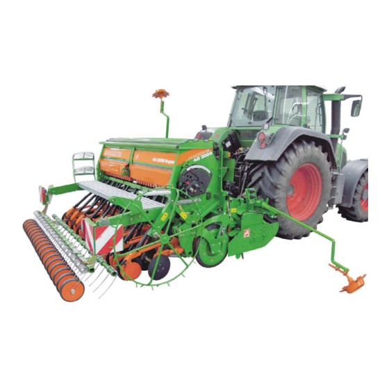
Product description Product description Components of the AMAZONE seeding combination Fig. 7 (A) AMAZONE soil tillage implement (B) AMAZONE roller (C) AMAZONE pack top seed drill AD 3000 Super AD 3000 Super BAH0107-0 02.20... -
Page 37: Assembly Groups Of The Ad 3000 Super Pack Top Seed Drill
Product description Assembly groups of the AD 3000 Super pack top seed drill Fig. 8 (1) Seed hopper (4) RoTeC Control coulters (2) Star wheel (5) Roller harrow, optionally exact following harrow (3) Vario gearbox (6) Loading board (7) Track marker, installed on the soil tillage implement AD 3000 Super BAH0107-0 02.20... - Page 38 Product description (1) Normal seed metering wheel / fine seed metering wheel (adjustable for seed metering) (2) Seeding shaft (3) Seed housing (4) Sliding shutter (5) Bottom flap (6) Bottom flap shaft Fig. 9 (1) Lay shaft to drive the tramline seed metering wheels (2) Lay shaft bearing (3) Lay shaft coupling with solenoid...
-
Page 39: Safety And Protective Equipment
Product description Safety and protective equipment (1) Handrail Fig. 12 (1) The road safety bar covers the tines of the exact following harrow that protrude into the traffic space. Fig. 13 AD 3000 Super BAH0107-0 02.20... -
Page 40: Overview - Supply Cable / Hydraulic Hose Lines
Product description Overview – Supply cable / hydraulic hose lines 4.4.1 Supply cable Description Function Implement plug Data transfer implement/job computer/control terminal Plug (7-pin) Connection to the lighting system for road travel 4.4.2 Identification of the hydraulic hose lines All hydraulic hose lines have handles with coloured markings and a code number or code letter to assign the respective hydraulic function to the pressure line of a tractor control unit. -
Page 41: Connection And Function Of The Tractor Control Units
Product description 4.4.3 Connection and function of the tractor control units Identification Connection of the of the hydraulic Function when actuating the tractor control unit tractor control unit hose lines Track marker on the soil tillage implement Lifting and lowering, alternating Single yellow acting... -
Page 42: Transportation Equipment
Product description Transportation equipment Fig. 15 only implements with exact following harrow: (1) Road safety bar, two-part Fig. 15 Fig. 16 (1) 2 rear lights (2) 1 licence plate holder (3) 2 rear-facing warning signs (4) 2 side-facing warning signs (not permitted in Germany and several other countries) Fig. -
Page 43: Proper Use
is mounted on an AMAZONE soil tillage implement with roller approved for this purpose is coupled to the tractor three-point hitch together with the soil tillage implement and is operated by one person. -
Page 44: Approved Amazone Implement Combinations
4.6.1 Approved AMAZONE implement combinations The AD 3000 Super pack top seed drill may only be combined with the following AMAZONE implements listed in the table. The combination of an AD 3000 Super with other implement is considered improper use and is therefore forbidden. -
Page 45: Danger Areas And Danger Points
Product description Danger areas and danger points The danger area is the area around the machine in which people can be caught: by work movements made by the implement and its tools by materials or foreign bodies thrown out of the implement ... -
Page 46: Rating Plate And Ce Mark
Product description Rating plate and CE mark The figure shows the arrangement of the rating plate and the CE mark on the implement. The CE mark indicates compliance with the stipulations of the valid EU directives. Fig. 20 The following information is specified on the rating plate and the CE mark: (1) Implement ID no. -
Page 47: Technical Data
Product description Technical data Pack top seed drill AD 3000 SUPER Working width Transport width 3.04 without extension Hopper content with extension 1000 Number of rows Row spacing [cm] 12.5 Medium WS coulter [km/h] 5 - 6 working speed Maximum [km/h] working speed Number of rows... -
Page 48: Technical Data For Calculating The Tractor Weight And The Tractor Axle Loads
Product description 4.10.1 Technical data for calculating the tractor weight and the tractor axle loads The technical data [total weight (G ) and distance (d)] is needed to calculate the tractor weights and tractor axle loads, see page 86. The permissible total weight (G ) of the rear- mounted implement combination is obtained from the sum of the weights listed in the following... -
Page 49: Tractor Equipment
Product description 4.11 Tractor equipment Minimum tractor conditions for proper operation of the implement Power AD 3000 Super Starting at 81 kW (110 HP) requirement Battery voltage 12 V (volts) Electrical equipment Lighting socket 7-pin See section Tractor control units "Overview –... -
Page 50: Structure And Function
Structure and function Fig. 24 The AMAZONE AD pack top seed drill is used as part of a cultivation combination with an AMAZONE soil tillage implement (Fig. 24/1) and AMAZONE roller (Fig. 24/2). The AD pack top seed drill allows precise seed placement, uniform placement depth and coverage of the seed, and a track-free, well-structured field after cultivation. - Page 51 The roller (Fig. 24/C) serves to reconsolidate the soil. AMAZONE provides the suitable roller for any seed type and any soil. The seed drill may only be combined with the approved AMAZONE rollers, see section "Approved AMAZONE implement combinations", page 44.
- Page 52 Structure and function The AMAZONE KWM wedge ring roller with matrix tyre profile is characterised by two particularly good properties. The wedge ring roller with matrix tyre profile has particularly good self-propulsion and produces lots of fine soil to fill the seed rows.
-
Page 53: Amazone Amalog+ Control Terminal
Structure and function AMAZONE AmaLog+ control terminal Implements with start wheel and Vario gearbox are equipped with the AmaLog+ control terminal. The AmaLog+ control terminal with an integrated computer is used to control and monitor the seed drill. One of these functions is the control of the tramline control and the tramline marker. -
Page 54: Seed Hopper And Loading Board
Structure and function Seed hopper and loading board The cover protects the contents of the seed hopper from water and dust. The seed hopper is filled from the loading board, on the back of the seed drill. The hopper extension enlarges the volume of the seed hopper, see section "Technical data", page Fig. -
Page 55: Rapeseed Insert
Structure and function Rapeseed insert The rapeseed insert (Fig. 33/1) reduces the holding capacity of the seed hopper. The rapeseed insert is used for readily flowing seed, such as rapeseed and turnips, which are sown at low seed densities. The agitator shaft must not rotate if the rapeseed insert is installed in the seed hopper. -
Page 56: Seeding Shaft Drive
Structure and function Seeding shaft drive The seed is metered by the metering wheels in the seed housings. The metering wheels are attached to the seeding shaft. The star wheel (Fig. 35/1) drives the seed metering wheels via the Vario gearbox. The speed of the seeding shaft is regulated depending on the working speed. -
Page 57: Metering
Structure and function Metering The seed is carried in the seed hopper. The seed goes into the seed housing through adjustable openings (Fig. 37/1). Each seed housing has an opening. The opening size is adjusted with the sliding shutters. The seed is metered either by the normal seed metering wheel (Fig. -
Page 58: Setting Values
Structure and function 5.7.1 Setting values Bottom flap position Seed Sliding Agitator shaft Seed metering shutter support wheel position less than using 6 g (rapeseed) 50 g (cereals) Normal open Triticale Normal ¾ open Barley Normal open Wheat Normal ¾ open Spelt Normal open... - Page 59 Structure and function Seed Sliding Bottom flap Agitator shaft Seed metering shutter position support wheel position Flax (dressed) Normal ¾ open Millet Normal ¾ open Lupins Normal ¾ open Lucerne Normal ¾ open Lucerne Fine ¾ open Oilseed Normal ¾ open (wet dressed) Oilseed Fine...
-
Page 60: Normal And Fine Seed Metering Wheel
Structure and function 5.7.2 Normal and fine seed metering wheel The seed metering wheel consists of Normal seed metering wheel (Fig. 38/1) Fine seed metering wheel (Fig. 38/2). For seeding with the normal seed metering wheel, the normal and fine seed metering wheel are linked to each other and both rotate ... -
Page 61: Bottom Flaps
Structure and function 5.7.5 Bottom flaps The gap between the seed metering wheel and the bottom flap (Fig. 41/1) depends on the size of the seed. The bottom flap lever (Fig. 41/2) is used to make adjustments. The bottom flaps are spring suspended for gentle metering of the seed. -
Page 62: Slide Gate
Structure and function 5.7.6 Slide gate The sliding shutters (Fig. 43) are used to adjust the opening between the seed hopper and the metering housing according to the seed. The sliding shutters (Fig. 43) latch into one of three positions: closed 3/4 open open... -
Page 63: Seed Rate Calibration
Structure and function 5.7.8 Seed rate calibration When calibrating the seed rate, the later field pass is simulated by rotating the star wheel (Fig. 46). The seed metered in the process is collected and weighed. The required seeding shaft speed is calculated from the simulated area (e.g. - Page 64 Structure and function The number of crank turns on the star wheel depends on the seed drill working width (Fig. 48/1). The number of star wheel rotations (Fig. 48/2) is based on an area of 1/40 ha (250 m ) or ...
- Page 65 Structure and function The desired seed rate is adjusted with the gearbox lever of the Vario gearbox. The correct gearbox position is determined during seed calibration. To do so, several calibration procedures are often required. With the values from the first calibration procedure, the required gearbox position can be immediately calculated.
-
Page 66: Rotec Control Coulter
Structure and function RoTeC Control coulter The RoTeC Control coulter (Fig. 52/1) is used for seed placement on ploughed or mulched soil, even with large quantities of straw and plant residues. Due to the support of the coulter on the depth control disc / wheel (Fig. - Page 67 Structure and function The adjust the seed placement depth, the depth control disc/wheel (see Fig. 55) can be engaged in 3 holes on the coulter removed if the seed placement depth is not reached. Hole Placement Shallow Seeding without depth control disc / Deep depth control wheel...
-
Page 68: Coulter Pressure And Seed Placement Depth
Structure and function Coulter pressure and seed placement depth Adaptation of the coulter pressure to the soil is required to achieve uniform seed placement depth. The coulter pressure must be set higher on heavy soils than on light soils. The coulter pressure is adjusted centrally by means of a crank handle or hydraulically. -
Page 69: Coulter Pressure Adjustment, Hydraulically Actuated
Structure and function 5.9.2 Coulter pressure adjustment, hydraulically actuated The coulter pressure can be adapted to the soil during operation when changing to heavy soil. The coulter pressure is adjusted hydraulically. Two pins (Fig. 58/1) in an adjuster segment act as the stop for the hydraulic cylinder. -
Page 70: Exact Following Harrow
Structure and function 5.10 Exact following harrow The exact following harrow (Fig. 60/1) evenly covers the seeds deposited in the seed furrows with loose earth and smoothes the ground. The following are adjustable the exact following harrow tine setting ... -
Page 71: Exact Following Harrow Tine Position
Structure and function 5.10.1 Exact following harrow tine position Exact following harrow tine position Distance "A" = 230 to 280 mm When correctly set, the harrow tines of the exact following harrow should: lie horizontally on the ground and ... -
Page 72: Exact Following Harrow Pressure
Structure and function 5.10.2 Exact following harrow pressure The exact following harrow pressure determines the tillage intensity of the exact following harrow and depends on the soil texture. To achieve uniform coverage of the seed row with soil, the exact following harrow pressure must be set higher on heavy soil than on light soil. -
Page 73: Roller Harrow With Contour Guidance
Structure and function 5.11 Roller harrow with contour guidance The roller harrow consists of harrow tines (Fig. 66/1), press rollers (Fig. 66/2). The harrow tines close the seed furrows. The press rollers press the seeds into the furrows. Better soil contact means more humidity is available for germination. -
Page 74: Tramlines
Structure and function 5.12 Tramlines Tramlines can be created on the field. Tramlines are seed-free tracks for fertilising and plant care implement used later. Fig. 69 Fig. 70 The AmaLog+ control terminal controls the creation of the tramlines (A). The tramline counter C counts the field passes. When creating tramlines, the tramline counter C shows the number "0"... -
Page 75: Tramline Control, Tabular Determination
Structure and function 5.12.1 Tramline control, tabular determination The required tramline control can be found in the table. The tramline control is derived from the desired tramline spacing and the working width of the seed drill. Other adjustable tramline controls can be found in the "Control terminal" operating manual. Seed drill working width Tramline control 3.0 m... -
Page 76: Tramline Control, Graphic Determination
Structure and function 5.12.2 Tramline control, graphic determination The graph (Fig. 72) shows examples for creating tramlines. Read the required values from the graph and enter the values as required on the control terminal. Column A: Working width of the seed drill ................3 m Column B: Tramline spacing (working width of the fertiliser spreader) ........ - Page 77 Structure and function Fig. 72 AD 3000 Super BAH0107-0 02.20...
-
Page 78: Functional Description
Structure and function 5.12.3 Functional description When creating tramlines, the tramline seed metering wheels (Fig. 73/1) are immobilised and the tramline coulters do not deposit any seed in the soil. The tramline seed metering wheels (Fig. 73/1) can rotate freely on the seeding shaft. The tramline seed metering wheels are driven by the gear wheels (Fig. -
Page 79: 5.12.3.1 Lay Shaft Coupling, Electrically Actuated
Structure and function 5.12.3.1 Lay shaft coupling, electrically actuated A solenoid (Fig. 75/2) actuates the lay shaft coupling (Fig. 75/1). The solenoid is controlled by the AmaLog+ control terminal. The control terminal monitors the tramline control and issues an alarm if there is an error with the lay shaft. -
Page 80: One-Sided Switching
Structure and function 5.12.4 One-sided switching Fig. 76 Figure (Fig. 72) shows examples for creating tramlines using tramline controls 4, 6 and 8. During the first field pass, it may be necessary to operate the seed drill with half the working width (part-width section). -
Page 81: Tramline Control 2 And 21
Structure and function 5.12.5 Tramline control 2 and 21 Fig. 78 (Fig. 78) shows examples of creating tramlines with tramline control 2 and 21. When tramlines are created with the tramline control 2 and 21, tramlines are created when driving out and driving back on the field. -
Page 82: Track Marker
Structure and function 5.14 Track marker Operate the track markers on the soil tillage implement as instructed in the the "Soil tillage implement" operating manual. It is possible to set: the length of the track marker the working intensity of the track marker, depending on the soil type. -
Page 83: Initial Operation
Initial operation Initial operation This section contains information on initial operation of your implement on how to check if you may mount the implement onto your tractor. Before operating the implement for the first time the operator must have read and understood the operating manual. -
Page 84: Checking The Suitability Of The Tractor
Initial operation Checking the suitability of the tractor WARNING Danger of breaking during operation, insufficient stability and insufficient tractor steering and braking power on improper use of the tractor! Check the suitability of your tractor before you mount or hitch the implement onto the tractor. -
Page 85: Calculating The Actual Values For The Total Tractor Weight, Tractor Axle Loads And Tyre Load-Bearing Capacity, As Well As The Required Minimum Ballast Weight
Initial operation 6.1.1 Calculating the actual values for the total tractor weight, tractor axle loads and tyre load-bearing capacity, as well as the required minimum ballast weight The permissible total tractor weight, specified in the vehicle documentation, must be greater than the sum of the ... -
Page 86: Data Required For The Calculation (Attached Implement)
Initial operation 6.1.1.1 Data required for the calculation (attached implement) Fig. 83 Tractor empty weight Refer to the tractor operating manual or registration document Front axle load of the empty tractor Rear axle load of the empty tractor Total weight of rear-mounted implement or see section "Technical data rear ballast for calculating the tractor weight and the... -
Page 87: Calculation Of The Required Minimum Ballast Weight At The Front G
Initial operation 6.1.1.2 Calculation of the required minimum ballast weight at the front G of the tractor to V min ensure steering capability In the table (section 6.1.1.2), enter the numeric value for the calculated minimum ballast weight G that is required on the front V min... -
Page 88: Table
Initial operation 6.1.1.7 Table Actual value according to Permissible value Double the calculation according to permissible tyre the tractor operating load-bearing manual capacity (2 tyres) Minimum ballast weight front/rear Total weight Front axle load Rear axle load ... -
Page 89: Secure The Tractor / Implement Against Unintentional Starting And Rolling Away
Initial operation Secure the tractor / implement against unintentional starting and rolling away Switch off the tractor PTO shaft. Park the tractor and the implement on solid, level ground. Lower the raised, unsecured implement/raised, unsecured implement parts. This prevents accidental lowering. Shut down the tractor engine. -
Page 90: Coupling And Uncoupling The Implement
Coupling and uncoupling the implement Coupling and uncoupling the implement The pack top seed drill can be parked solo, on the parking supports Fig. 84 mounted, on the soil tillage implement Fig. 85 This section describes the coupling and uncoupling of the soil tillage implement on the tractor. - Page 91 Coupling and uncoupling the implement When coupling and uncoupling implements, follow the instructions given in the section "Safety instructions for the operator". CAUTION Before adjustment, maintenance and repair work couple the pack top seed drill and the soil tillage implement. ...
-
Page 92: Hydraulic Hose Lines
Coupling and uncoupling the implement Hydraulic hose lines WARNING Danger of infection from escaping hydraulic fluid at high pressure! When coupling and uncoupling the hydraulic hose lines, ensure that the hydraulic system is depressurized on both the implement and tractor sides. -
Page 93: Disconnecting The Hydraulic Hose Lines
Coupling and uncoupling the implement 1. Clean the coupling part. 2. Put the tractor control units into the float position. 3. Connect the hydraulic lines In doing so, observe the labels on the hydraulic lines, see section 4.4. Fig. 87 7.1.2 Disconnecting the hydraulic hose lines 1. -
Page 94: Safety Instructions For Coupling The Seed Drill
Coupling and uncoupling the implement Safety instructions for coupling the seed drill WARNING Danger of breaking during operation, insufficient stability and insufficient tractor steering and braking power on improper use of the tractor! You may only connect the implement to or mount it on tractors that are suitable for the purpose. - Page 95 Coupling and uncoupling the implement WARNING Risk of energy supply failure between the tractor and the implement through damaged power lines! During coupling, check the course of the power lines. The supply lines must give slightly without tension, bending or rubbing on all movements of the connected implement.
-
Page 96: Coupling And Uncoupling The Implement Combinations - Overview
Page 116 system roller frame Simplex Prismatic roller Section 7.2.2 Section 7.2.3 ── ── suitable Page 97 Page 100 for AMAZONE 1-tube roller frame system Simplex Prismatic roller Section 7.2.6 Section 7.2.7 ── ── suitable Page 112 Page 116 for AMAZONE 2-tube... -
Page 97: Sg (Made By Güttler) ● Simplex Prismatic Roller Sx-45 Su (Made By Güttler)
Coupling and uncoupling the implement 7.2.2 Mounting the seed drill on KG/KE/KX 00 soil tillage implements with 1-tube system roller frame ● Tooth packer roller PW 500 ● Wedge ring roller KW 520 on KG/KE/KX 01 soil tillage implements with 1-tube system roller frame ●... - Page 98 Coupling and uncoupling the implement 1. Direct persons away from the danger area between the soil tillage implement and the pack top seed drill. Fig. 91 2. Drive the soil tillage implement in reverse towards the pack top seed drill parked on the parking supports.
- Page 99 Coupling and uncoupling the implement 8. Raise the combination so that the parking supports are just above the ground. 9. Remove the parking supports (Fig. 95/1). 10. Park the combination without parking supports. 11. Apply the tractor parking brake, switch the tractor engine off and remove the ignition key.
-
Page 100: Uncoupling The Seed Drill From Kg/Ke/Kx 00 Soil Tillage Implements With 1-Tube
Coupling and uncoupling the implement 7.2.3 Uncoupling the seed drill from KG/KE/KX 00 soil tillage implements with 1-tube system roller frame ● Tooth packer roller PW 500 ● Wedge ring roller KW 520 from KG/KE/KX 01 soil tillage implements with 1-tube system roller frame ●... - Page 101 Coupling and uncoupling the implement 7. Slightly raise the combination and insert the parking supports (Fig. 98/1) into the square tubes of the pack top seed drill. 8. Lower the combination until the pack top seed drill is standing on the parking supports.
- Page 102 Coupling and uncoupling the implement 11. Remove the top link (Fig. 100/1). 12. Direct persons away from the danger area between the soil tillage implement and the pack top seed drill. 13. Raise the soil tillage implement and carefully pull it forwards without touching the pack top seed drill.
-
Page 103: Mounting The Seed Drill On Kg/Ke/Kx 00 Soil Tillage Implements With 2-Tube System Roller Frames ● Tooth Packer Roller Pw 600 ● Wedge Ring Roller Kw 580
Coupling and uncoupling the implement 7.2.4 Mounting the seed drill on KG/KE/KX 00 soil tillage implements with 2-tube system roller frames ● Tooth packer roller PW 600 ● Wedge ring roller KW 580 The pack top seed drill is equipped with ... - Page 104 Coupling and uncoupling the implement 1. Direct persons away from the danger area between the soil tillage implement and the pack top seed drill. Fig. 105 2. Drive the soil tillage implement in reverse towards the pack top seed drill parked on the parking supports.
- Page 105 Coupling and uncoupling the implement 7. Fasten the pack top seed drill onto the roller with 2 turnbuckles (Fig. 109/1). 8. Secure each pin (Fig. 109/2) with a cotter pin. 9. Tighten and lock the turnbuckles (lock nut). Fig. 109 10.
- Page 106 Coupling and uncoupling the implement 12. Raise the combination so that the parking supports are just above the ground. 13. Remove the parking supports (Fig. 111/1). 14. Park the combination without parking supports. 15. Apply the tractor parking brake, switch the tractor engine off and remove the ignition key.
- Page 107 Coupling and uncoupling the implement 17. Pull out the top carrying arm pin (Fig. 113/1). Adjust the top link if the carrying arm pin cannot be loosened. Fig. 113 18. Put the carrying arm pin (Fig. 114/1) into parking position and secure with a linch pin. 19.
-
Page 108: Uncoupling The Seed Drill From Kg/Ke/Kx 00 Soil Tillage Implements With 2-Tube System Roller Frame Tooth Packer Roller Pw 600 Wedge Ring Roller Kw 580
Coupling and uncoupling the implement 7.2.5 Uncoupling the seed drill from KG/KE/KX 00 soil tillage implements with 2-tube system roller frame Tooth packer roller PW 600 Wedge ring roller KW 580 DANGER Empty the hopper before decoupling the pack top seed drill from the soil tillage implement. - Page 109 Coupling and uncoupling the implement 7. Fix the carrying arms with the top carrying arm pins (Fig. 116/1). Line up the holes by adjusting the top link. 8. Secure the carrying arm pins with linch pins. Fig. 116 9. Slightly raise the combination and insert the parking supports (Fig.
- Page 110 Coupling and uncoupling the implement 11. Apply the parking brake, switch the tractor engine off and remove the ignition key. 12. Remove both catch hook lock pins (Fig. 118/1). Fig. 118 13. Remove the 2 turnbuckles (Fig. 119/1). Fig. 119 AD 3000 Super BAH0107-0 02.20...
- Page 111 Coupling and uncoupling the implement 14. Remove the top link (Fig. 120/1). 15. Direct persons away from the danger area between the soil tillage implement and the pack top seed drill. 16. Lower the soil tillage implement and carefully pull it forwards without touching the pack top seed drill.
-
Page 112: Trapeze Ring Roller Trw 600 ● Simplex Prismatic Roller Sx-50 Sg (Made By Güttler) ● Simplex Prismatic Roller Sx-56 Su (Made By Güttler)
Coupling and uncoupling the implement 7.2.6 Mounting the seed drill on KG/KE/KX 01 soil tillage implements with 2-tube system roller frame ● Tooth packer roller PW 600 ● Wedge ring roller KW 580 ● Wedge ring roller with matrix tyre profile KWM 600 ●... - Page 113 Coupling and uncoupling the implement 1. Remove the coupling pieces (Fig. 124/1). 2 coupling pieces can be found in parking position on the soil tillage implement. They serve as a mechanical lock after coupling the combination. Fig. 124 2. Direct persons away from the danger area between the soil tillage implement and the pack top seed drill.
- Page 114 Coupling and uncoupling the implement 4. Pick up the seed drill bearing (Fig. 126/1) with the soil tillage implement catch hooks (Fig. 126/2). Fig. 126 5. Apply the tractor parking brake, switch the tractor engine off and remove the ignition key.
- Page 115 Coupling and uncoupling the implement 10. Raise the combination so that the parking supports are just above the ground. 11. Remove the parking supports (Fig. 129/1). 12. Park the combination without parking supports. 13. Apply the tractor parking brake, switch the tractor engine off and remove the ignition key.
-
Page 116: Trapeze Ring Roller Trw 600
Coupling and uncoupling the implement 7.2.7 Uncoupling the seed drill from KG/KE/KX 01 soil tillage implements with 2-tube system roller frame ● Tooth packer roller PW 600 ● Wedge ring roller KW 580 ● Wedge ring roller with matrix tyre profile KWM 600 ●... - Page 117 Coupling and uncoupling the implement 7. Remove the coupling pieces. 7.1 Raise the combination so that the parking supports are just above the ground. 7.2 Apply the tractor parking brake, switch off the engine and remove the ignition key. 7.3 Remove the linch pins (Fig. 132/1). Fig.
- Page 118 Coupling and uncoupling the implement 9. Slide 2 parking supports (Fig. 134/1) into the mounting until the stop. 10. Lower the combination until the pack top seed drill is standing on the parking supports. Fig. 134 11. Remove the top link (Fig. 135/1). Fig.
- Page 119 Coupling and uncoupling the implement 12. Direct persons away from the danger area between the soil tillage implement and the pack top seed drill. 13. Lower the soil tillage implement and carefully pull it forwards without touching the pack top seed drill. Fig.
-
Page 120: Uncoupling - Seeding Combination From The Tractor (All Types)
Coupling and uncoupling the implement 7.2.8 Uncoupling – Seeding combination from the tractor (all types) DANGER Danger: the uncoupled combination may roll away from the tractor. Set the combination down only on a level parking area with firm ground. Secure the combination against rolling away before uncoupling it. The pack top seed drill can be parked while mounted on the soil tillage implement. -
Page 121: Settings
Settings Settings WARNING Danger of crushing, shearing, cutting, being caught or drawn in, winding and knocks through: unintentional lowering of the implement raised using the tractor's three-point hydraulic system unintentional lowering of raised, unsecured implement parts unintentional start-up and rolling away of the tractor- implement combination. -
Page 122: Folding The Steps Up And Down
Settings Folding the steps up and down DANGER Never climb onto the steps and the loading board when the seed drill is parked on the supports (risk of tipping). Climbing up is only permitted when the seed drill is coupled to the soil tillage implement. - Page 123 Settings Fold the steps up and down carefully by hand. Only unfold the steps when the seed drill is coupled to the tractor or the soil tillage implement. 1. Hold onto the steps. 2. Release the mechanical transport lock (see above).
-
Page 124: Moving The Star Wheel Into Transport/Working Position
Settings Moving the star wheel into transport/working position 8.2.1 Moving the star wheel to the working position 1. Pull the star wheel out of the transport bracket (Fig. 143/1). The star wheel is secured with a linch pin (Fig. 143/2). Fig. -
Page 125: Move The Star Wheel To The Transport Position
Settings 8.2.2 Move the star wheel to the transport position 1. Raise the star wheel. 2. Swivel the bar (Fig. 145/1). Fig. 145 3. Fasten the star wheel in the transport bracket. 3.1 Loosen the linch pin (Fig. 146/1) and pull the star wheel off of the drive. -
Page 126: Fill The Seed Hopper
Settings Fill the seed hopper DANGER Never fill the seed drill when the seed drill is parked on the supports (risk of tipping). Before filling the seed hopper, couple the implement combination to the tractor. Observe the permissible fill levels and total weights. WARNING Risk of crushing in danger area under suspended loads/implement parts when filling the hopper, caused by... - Page 127 Settings 1. Couple the implement combination to the tractor. 2. Park the combination on a level surface. 3. Secure the tractor / implement against unintentional starting and rolling away. 4. Climb onto the loading board using the steps (Fig. 148/1). 5.
- Page 128 Settings 8. While filling the seed hopper, set the bottom flap lever (Fig. 150/1) to a position between 1 and 4. Always engage the bottom flap lever in the group of holes and secure it. Fig. 150 9.Fill the seed hopper ...
-
Page 129: Placing The Calibration Trays On The Funnel Rail
Settings Placing the calibration trays on the funnel rail 1. Pull the spring-loaded lever (Fig. 152/1) sideways out of the locking device. Fig. 152 2. Lower the funnel rail (Fig. 153/1). Fig. 153 3. Pull the calibration trays up out of the brackets. -
Page 130: Setting The Seed Rate
Settings Setting the seed rate 1. The required setting values can be found in the table "Setting values", page 58. 1.1 Seed metering wheel selection, see section "Seeding with the normal or fine seed metering wheel", page 130. 1.2 Sliding shutter position, see section "Adjusting the sliding shutters", page 133 1.3 Bottom flap position, see section "Bottom flap position", page 134... - Page 131 Settings 4. Turn the star wheel to the right until the holes (Fig. 158/1) of the fine seed metering wheels are visible. Fig. 158 Seeding with normal seed metering wheels 1. Turn the normal seed metering wheel on the seeding shaft by hand until the pin (Fig. 159/1) is visible in the hole.
-
Page 132: Seeding With Bean Seed Metering Wheels
Settings Seeding with fine seed metering wheel 1. Use the supplied key (Fig. 161/1) to press the pin into the normal seed metering wheel behind the hole until it reaches the stop. 2. Check whether the normal seed metering wheel is able to turn freely on the seeding shaft. -
Page 133: Adjusting The Sliding Shutters
Settings 8.5.3 Adjusting the sliding shutters This setting affects the seeding rate. Calibrate the seed rate after the adjustment. 1. Pull the calibration trays (Fig. 163) out of the brackets. After the adjustment work, attach the calibration trays back in the brackets. Fig. -
Page 134: Bottom Flap Position
Settings 8.5.4 Bottom flap position This setting affects the seeding rate. Calibrate the seed rate after the adjustment. 1. Set the bottom flap lever (Fig. 165/1) in the group of holes at the value from the table (see page 58). 2. -
Page 135: Agitator Shaft Support
Settings 8.5.5 Agitator shaft support This setting affects the seeding rate. Calibrate the seed rate after the adjustment. Seeding with agitator shaft support If the linch pin (Fig. 166/1) is inserted in the hole of the gearbox hollow shaft, the agitator shaft support is active. -
Page 136: Mounting The Rapeseed Insert
Settings 8.5.6 Mounting the rapeseed insert Switch off the agitator shaft drive before installing the rapeseed insert in the seed hopper. 1. Switch off the agitator shaft drive, see section "Agitator shaft support", page 135. Position the stirring pins (Fig. 168/2) vertically if the agitator shaft does not have any round stirring elements, see section Agitator shaft... -
Page 137: Calibrating The Seed Rate
Settings Calibrating the seed rate 1. Couple the seeding combination to the tractor. 2. Park the combination on a level surface. 3. Secure the tractor against unintentional start-up and unintentional rolling away. 4. Fill at least 1/3 of the seed hopper with seed (accordingly less for fine seed). 5. - Page 138 Settings Pre-calibrating the implement 11. Pre-calibrate the seed drill. Preturning creates the same conditions as when driving on the field later on. 11.1 Raise the star wheel. 11.2. Insert the calibration crank (Fig. 172/1) into the square tube of the star wheel. 11.3 Turn the star wheel clockwise (direction shown by the arrow) until the seed falls out of all seed housings into...
- Page 139 Settings Calibrating the seed rate 12. Calibrating the seed rate. 12.1 Turn the star wheel to the right by the number of crank turns specified in the table (Fig. 48, page 64). 12.2 Weigh the seed collected in the calibration trays. The supplied collapsible bucket is used to transfer the collected seed.
-
Page 140: Determining The Gearbox Setting Using The Calculating Disc Rule
Settings 13. The desired seed rate [kg/ha] is generally not achieved with the first calibration. Using the calibration values from the first calibration, determine the required gearbox setting values for the desired seed rate [kg/ha] using the calculating disc rule, see section "Determining the gearbox setting using the calculating disc rule", page 140. -
Page 141: Rotec Control Coulter
Settings RoTeC Control coulter 8.7.1 Adjusting and checking the seed placement depth The seed placement depth depends on the factors Soil type (light to heavy) Forward speed Coulter pressure Position of the depth control discs/wheels. Check the placement depth when one of the factors has changed. 1. -
Page 142: Adjusting The Depth Control Discs / Wheels
Settings 8.7.1.1 Adjusting the depth control discs / wheels If the desired placement depth cannot be achieved by adjusting the coulter pressure, adjust or remove all of the depth control discs/wheels equally, as described in this section. Engaging the depth control disc/wheel in one of the holes on the coulter 1. - Page 143 Settings Dismounting the depth control disc/wheel 1. Engage the shoulder of the lever beyond the group of holes (Fig. 176/1) into the slotted hole (Fig. 176/2). 2. Move the depth control disc/wheel in the slotted hole (Fig. 176/2) until the depth control disc/wheel is released from the locking mechanism (Fig.
-
Page 144: Coulter Pressure
Settings Coulter pressure This setting influences the placement depth of the seed. Check the placement depth after every adjustment. 8.8.1 Coulter pressure adjustment (manual adjustment) 1. Place the calibration crank on the setting spindle (Fig. 177) and set the coulter pressure. -
Page 145: Hydr. Coulter Pressureadjustment
Settings 8.8.2 Hydr. coulter pressureadjustment WARNING Direct people out of the danger area of the hydraulically operated components. 1. Actuate the control valve (green). Apply pressure to the hydraulic cylinder. 2. Apply the parking brake, switch the tractor engine off and remove the ignition key. 3. -
Page 146: Adjusting The Exact Following Harrow
Settings Adjusting the exact following harrow 8.9.1 Moving the exact following harrow to the working/transport position 8.9.1.1 Move the exact following harrow into working position The roller and the coulters force the soil outwards to different extents depending on the forward speed and condition of the soil. -
Page 147: Adjusting The Exact Following Harrow Tines By Rebolting The Brackets
Settings 8.9.2 Adjusting the exact following harrow tines by rebolting the brackets 1. Adjust the distance "A" (see section 5.10.1, page 71) by rebolting the exact following harrow bracket. 2. The exact following harrow has two adjuster segments. Make the same adjustments on both adjuster segments. -
Page 148: Setting The Exact Following Harrow Pressure
Settings 8.9.4 Setting the exact following harrow pressure 1. Tension the tension springs of the exact following harrow with the calibration crank. 2. Insert the pin (Fig. 184/2) in a hole beneath the lever (Fig. 184/1) and secure with a spring cotter pin. -
Page 149: Adjusting The Roller Harrow
Settings 8.10 Adjusting the roller harrow 8.10.1 Setting the pitch of the tines to the ground 1. Raise the implement until the harrow tines are directly above the ground, but not touching it. 2. Apply the tractor parking brake, switch the tractor engine off and remove the ignition key. 3. -
Page 150: Setting The Roller Contact Pressure
Settings 8.10.3 Setting the roller contact pressure 1. Move the implement on the field to the working position. 2. Swivel both handles (Fig. 187/1) up. Fig. 187 The two spring-loaded levers (Fig. 188/1) serve to adjust the roller contact pressure on the ground. - Page 151 Settings 4. Secure the position of the lever (Fig. 189/1) with a safety pin for the tube (Fig. 189/2). 5. Peg the second lever in the same hole of the hole group and secure it. The roller contact pressure is highest when the safety pin for the tube (Fig.
-
Page 152: Deactivating/Activating The Roller Harrow
Settings 8.10.4 Deactivating/activating the roller harrow 8.10.4.1 Deactivating the roller harrow (lifting) 1. Set the implement down on a level surface. 2. Briefly pull on the lever (Fig. 191/1) and remove the safety pin for the tube (Fig. 191/2). Fig. 191 3. -
Page 153: Activating The Roller Harrow (Lowering)
Settings 8.10.4.2 Activating the roller harrow (lowering) 1. Set the implement down on a level surface. 2. Take the safety pin for the tube that was inserted in the parking position. 3. Swivel the handle (Fig. 194/1) up. Fig. 194 4. -
Page 154: Moving The Track Marker To The Working / Transport Position
Settings 8.12 Moving the track marker to the working / transport position DANGER Each track marker has a mechanical lock. Secure the track markers when they are raised for transport immediately after work on the field. Unsecured track markers could unintentionally move to the working position and cause serious injury. -
Page 155: One-Sided Switching
Settings 8.13 One-sided switching With the one-sided switching, the left side of the seeding shaft can be shut off and seed delivery to the coulters can be interrupted. If the tramline seed metering wheels should also not spread any seed, the shutter slides for the tramline seed metering wheels must be closed. -
Page 156: Moving The Tramline Marker Into Working/Transport Position
Settings 8.14 Moving the tramline marker into working/transport position WARNING Direct people out of the danger area of the hydraulically operated components. When actuating the tractor control unit, the hydraulic cylinders of the track markers and of the tramline marker can be actuated simultaneously. -
Page 157: Move The Tramline Markers To The Transport Position
Settings 8.14.2 Move the tramline markers to the transport position 1. Lift the track discs hydraulically, if the track discs are lowered to create a track, refer to the "Control terminal" operating manual. 2. Apply the parking brake, switch the motor off and remove the ignition key. -
Page 158: Moving The Exact Following Harrow Road Safety Bar Into Road Transport/Parking Position
Settings 8.15 Moving the exact following harrow road safety bar into road transport/parking position 8.15.1 Moving the road safety bar into road transport position 1. Push the two-part road safety bar (Fig. 202/1) over the tine tips of the exact following harrow. -
Page 159: Transportation
Transportation Transportation DANGER In Germany and several other countries, the transportation of implements mounted on the tractor on public roads and routes is approved up to a width of 3.0 m. Transport of a combination over 3.0 m wide is only permitted on a transport vehicle in these countries. -
Page 160: Legal Regulations And Safety
Transportation Legal regulations and safety When driving on public streets or roads, the tractor and implement must comply with the national road traffic regulations (in Germany the StVZO and the StVO) and the accident prevention regulations (in Germany those of the industrial injury mutual insurance organisation). The vehicle keeper and driver are responsible for compliance with the statutory stipulations. - Page 161 Transportation Before driving off, read the section "Safety information for the operator" and check: that the permissible weight is not exceeded. that the supply lines are connected correctly the lighting system for damage, function and cleanliness. that the warning signs and yellow reflectors are clean and undamaged ...
- Page 162 Transportation WARNING Risk of crushing, cutting, being caught and/or drawn in, or impact from tipping and insufficient stability. Drive in such a way that you always have full control over the tractor with the attached implement. In so doing, take your personal abilities into account, as well as the road, traffic, visibility and weather conditions, the driving characteristics of the tractor and the connected or coupled implement.
- Page 163 Transportation WARNING During road transport, risk of stabbing injuries to other road users from uncovered, sharp spring tines of the exact following harrow! Road transport without a correctly fitted road safety bar is forbidden when the implement is equipped with an exact following harrow. WARNING Risk of stabbing from transporting with outer harrow elements folded out!
-
Page 164: Use Of The Implement
Use of the implement Use of the implement When using the implement, observe Section "Warning symbols on the implement", page 18 Section "Safety information for users", page Observing these sections is important for your safety. Fig. 205 WARNING Actuate the tractor control units only in the tractor cab. -
Page 165: Initial Operation
Use of the implement 10.1 Initial operation Before initial commissioning Section 12.5.2 Check the hydraulic hose lines and couplings. Page 189 Check all the components of the hydraulic system for leaks Section 12.7 Check the oil level, in the Vario gearbox Page 191 After the first 10 operating hours Section 12.5.2... -
Page 166: During Operation
Use of the implement 10.3 During operation 10.3.1 Overview of checks during operation Time interval Inspection Section Page after the first 30 to 50 m travelled at Check the seed placement depth working speed have been covered after changing from light to heavy soil and vice-versa ... -
Page 167: Seeding Check
Use of the implement 10.3.2 Seeding check During operation, the "AmaLog+" control terminal shows the status of the seed drill. The Vario gearbox is connected to the drive wheel by a chain. A sensor in the Vario gearbox records the rotation of the drive wheel and transmits the pulses to the control terminal. -
Page 168: Turning At End Of The Field
Use of the implement 10.4 Turning at end of the field DANGER After turning, with the corresponding pre-selection on the control terminal and when the tractor control unit is actuated, the opposite track marker is moved to the working position. 1. -
Page 169: Track Marker
Use of the implement 10.4.1 Track marker Raise the active track marker in the field before passing obstacles. Raising the track marker makes the tramline counter advance. Advancing of the tramline counter can be disabled, refer to the "AmaLog+" operating manual. After passing the obstacle, lower the track marker and check the tramline counter. -
Page 170: Emptying The Seed Hopper And Seed Housing
Use of the implement 10.5 Emptying the seed hopper and seed housing CAUTION Before working on the implement couple the pack top seed drill and the soil tillage implement. lower the implement combination onto level solid ground apply the tractor parking brake ... - Page 171 Use of the implement 1. Place the soil tillage implement with pack top seed drill on level ground. 2. Switch off the tractor engine and apply the tractor parking brake. When emptying the seed hopper, the tramline counter should not display "0".
- Page 172 Use of the implement 12. Empty the seed housing. 12.1 Raise the star wheel and lock it. 12.2 Insert the calibration crank (Fig. 210/1) into the square tube of the star wheel. 12.3 Fill the calibration trays by turning the star wheel clockwise until the seed housings are empty.
-
Page 173: Faults
Faults Faults WARNING Danger of crushing, shearing, cutting, being caught or drawn in, winding and knocks through: unintentional lowering of the implement raised using the tractor's three-point hydraulic system unintentional lowering of raised, unsecured implement parts unintentional start-up and rolling away of the tractor- implement combination. -
Page 174: Residual Seed Quantity Display
Faults 11.1 Residual seed quantity display A visual and acoustic warning is given when the residual quantity in the hopper is undercut (when the fill level sensor is correctly set). The residual quantity should be large enough to prevent fluctuations in the seed rate. 11.2 Deviations between the set and actual seed rate Possible causes that can lead to a deviation between the set and actual seed rate:... -
Page 175: Maintenance And Repairs
Maintenance and repairs Maintenance and repairs 12.1 Maintenance schedule The time intervals, kilometre readings and maintenance intervals specified in any third party documentation supplied shall have priority over the maintenance schedule. Before starting work (every day) Section 12.5.1 Visual inspection of the upper and lower link pins Page 188 Section 12.5.2 Check the hydraulic hose lines and couplings... -
Page 176: Lubrication Schedule
Maintenance and repairs 12.2 Lubrication schedule Lubrication Number of Lubrication Component Note points grease nipples interval Fig. 211/1 Tramline marker 1x annually Lubricants, see section "Oils and greases", page 194. 12.2.1 Lubrication points Fig. 211 AD 3000 Super BAH0107-0 02.20... -
Page 177: Safety
Maintenance and repairs 12.3 Safety WARNING Danger of crushing, shearing, cutting, being caught or drawn in, winding and knocks through: unintentional lowering of the implement raised using the tractor's three-point hydraulic system unintentional lowering of raised, unsecured implement parts ... -
Page 178: Safety When Cleaning The Implement
Maintenance and repairs WARNING Risk of crushing, shearing, cutting, being caught and/or drawn in, or impact through unprotected danger points. Mount protective equipment, which you removed when cleaning, maintaining and repairing the implement. Replace defective protective equipment with new equipment. ... -
Page 179: Safety When Working On The Hydraulic System
Maintenance and repairs The pictogram serves as a reminder never to aim the cleaning jet of the (hot water) high pressure cleaner directly on electrical components lubrication points and bearings the rating plate, warning symbols, stickers and design foils. -
Page 180: Installations
Maintenance and repairs 12.4 Installations 12.4.1 Shutdown of the implement over a long period of time 1. The RoTeC Control coulters must be cleaned and dried thoroughly must be protected against rust with an environmentally-friendly anti-corrosion agent. 2. Relieve the roller harrow to unload the formed rubber elements, see section "Setting the roller contact pressure", page 150. - Page 181 Maintenance and repairs 3. Fold down the lay shaft (Fig. 216/1). Fig. 216 At the same time, a bracket (Fig. 217/1) that axially secures the lay shaft will be pulled out of the recess in the seed housing. Fig. 217 The solenoid (if present) is folded down along with the lay shaft.
-
Page 182: Folding Up The Lay Shaft
Maintenance and repairs 12.4.3 Folding up the lay shaft 4. Fold up the lay shaft. When doing so, insert the bracket (Fig. 219/1) that secures the lay shaft in an axial position into the recess of a seed housing. 5. -
Page 183: Setting The Tramline Spacing, Track Width And Wheelmark Width
Maintenance and repairs 12.4.4 Setting the tramline spacing, track width and wheelmark width 1. Fold down the lay shaft, see section "Folding down the lay shaft", page 180. 2. Mark new tramline seed metering wheels by inserting the fine seed metering wheel brushes (Fig. - Page 184 Maintenance and repairs 4. Remove (Fig. 224/1) bolts. 5. Loosen the hexagon socket screws (Fig. 224/2). 6. Push the swivel bearing and the driving pinion onto the lay shaft. 7. Screw the swivel bearing onto the new tramline seed housings. Fig.
-
Page 185: Installing The Bean Metering Wheels
Maintenance and repairs 12.4.5 Installing the bean metering wheels This setting affects the seeding rate. Check the setting with a calibration test. 1. Fold down the lay shaft, see section "Folding down the lay shaft", page 180. 2. Do not remove the detent plate for the bottom flaps. - Page 186 Maintenance and repairs 7. The bean seeding shaft is installed in reverse sequence. 8. Mount the gear wheel (Fig. 228/1) onto the bean seeding shaft. Fig. 228 9. Remove the triangular carriers (Fig. 229/1) of the bean seed metering wheels for those bean seed metering wheels that are to be switched off later on to create the tramlines.
- Page 187 Maintenance and repairs 10. Fold up the lay shaft, see section "Folding up the lay shaft", page 182. 10.1 Make sure that the cogs (Fig. 230/1) of the gear wheels are meshed. Fig. 230 10.2 Rotate the axial lock (Fig. 231/1) so that the short arm is supported in the recess on the seed housing.
-
Page 188: Maintenance
Maintenance and repairs 12.5 Maintenance 12.5.1 Visual inspection of the upper and lower link pins Adhere to the inspection intervals, see section "Maintenance schedule", page 175. WARNING Risk of contusions, catching, and knocks when the implement unexpectedly releases from the tractor! Check the upper and lower link pins for visible defects whenever the implement is coupled. -
Page 189: Visual Check Of The Hydraulic Hose Lines And Couplings
Have any defects on the hydraulic hose lines immediately repaired by a specialist workshop. Use only original AMAZONE hydraulic hose lines. Have the hydraulic hose lines checked for proper functioning by a specialist workshop at least every quarter. -
Page 190: Checking Roller Chains And Chain Wheels
Maintenance and repairs 12.6 Checking roller chains and chain wheels On all roller chains, at the end of the planting season Clean (including the chain wheels and chain tensioner) Check Lubricate with low-viscosity mineral oil. 12.6.1 Bottom flaps basic position Adhere to the inspection intervals, see section "Maintenance schedule", page 175. -
Page 191: Vario Gearbox, Check The Oil Level
Maintenance and repairs 12.7 Vario gearbox, check the oil level Adhere to the inspection intervals, see section "Maintenance schedule", page 175. 1. Position the implement on a horizontal surface. 2. Check the oil level. The oil level must be visible in the oil sight glass (Fig. -
Page 192: Repairs (Specialist Workshop Work)
Maintenance and repairs 12.8 Repairs (specialist workshop work) WARNING The work described in the Repairs section may only be performed by a specialist workshop. 12.8.1 Checking the hydraulic hose lines Adhere to the inspection intervals, see section "Maintenance schedule", page 175. Check the hydraulic hose lines and fix any defects (specialist workshop): ... -
Page 193: 12.8.1.1 Safety When Working On Hydraulic Hose Lines
When installing or removing hydraulic hose lines, observe the following safety instructions: Only a specialist workshop may perform work on the hydraulic system. Use only genuine AMAZONE hydraulic hose lines! Ensure cleanliness. As a matter of principle, you must install the hydraulic hose lines such that, in all implement situations, ... -
Page 194: Oils And Greases
Maintenance and repairs 12.9 Oils and greases Hydraulic oil Keep out of the reach of children May not enter the ground or water Dispose of properly. 12.9.1 Vario gearbox gear oil Vario gearbox 0.9 litres Total filling quantity Wintershall Wintal UG22 WTL-HM (ex-works) Vario gearbox Gear oil (selectable) -
Page 195: Bolt Tightening Torques
Maintenance and repairs 12.10 Bolt tightening torques The tightening torques listed in this table do not apply for coated bolts. If coated bolts are fitted, you can find the tightening torques beside the instruction. 10.9 12.9 M 8x1 M 10 16 (17) M 10x1 M 12... - Page 198 H. DREYER GmbH & Co. KG Postfach 51 Tel.: + 49 (0) 5405 501-0 D-49202 Hasbergen-Gaste email: amazone@amazone.de Germany http:// www.amazone.de...
Need help?
Do you have a question about the AD 3000 Super Classic Line and is the answer not in the manual?
Questions and answers