
Related Manuals for Amazone Precea 3000-A


Summary of Contents for Amazone Precea 3000-A
- Page 1 Original operating manual Pack top precision airplanter Precea 3000-A Precea 3000-ACC Precea 3000-AFCC SmartLearning www.amazone.de...
- Page 2 Please enter the identification data of the implement. The identification data can be found on the rating plate.
-
Page 3: Table Of Contents
Layout of the warning symbols 5.5.2 Fertiliser metering unit 4.5.3 Description of the warning symbols 5.5.3 Micropellet metering unit Rating plate on the implement Coulters Compressed air fan 5.6.1 PreTeC mulch seeding coulter Grain singling unit MG6659-EN-GB | F.1 | 25.10.2022 | © AMAZONE... - Page 4 Relieving the hole covering rollers 140 6.3.11 Adjusting the PreTeC mulch seeding coulter Parking the PreTeC coulter 6.3.12 Creating tramlines Disconnecting the supply lines from the front-mounted hopper 6.3.13 Calibrating the electrically driven fertiliser metering unit MG6659-EN-GB | F.1 | 25.10.2022 | © AMAZONE...
- Page 5 10.1.13 Checking the hydraulic hose lines 10.1.14 Cleaning the fan rotor 10.1.15 Cleaning the cyclone separator 10.1.16 Cleaning the suction basket 10.1.17 Cleaning the filling auger 10.1.18 Cleaning the fertiliser hopper 10.1.19 Cleaning the fertiliser metering unit MG6659-EN-GB | F.1 | 25.10.2022 | © AMAZONE...
-
Page 7: About This Operating Manual
CAUTION Indicates a threat with low risk for light or moderately severe physical injuries. 1.1.2 Further instructions CMS-T-00002416-A.1 IMPORTANT Indicates a risk for damage to the implement. MG6659-EN-GB | F.1 | 25.10.2022 | © AMAZONE... -
Page 8: Instructions
CMS-T-005678-B.1 Reactions to instructions are marked with an arrow. Example: 1. Instruction 1 Reaction to instruction 1 2. Instruction 2 1.1.3.2 Alternative instructions CMS-T-00000110-B.1 Alternative instructions are introduced with the word "or". MG6659-EN-GB | F.1 | 25.10.2022 | © AMAZONE... -
Page 9: Lists
Lists without an essential order are shown as a list with bullets. Example: Point 1 Point 2 1.1.5 Item numbers in figures CMS-T-000023-B.1 A framed number in the text, e.g. a 1 , indicates an item number in an adjacent figure. MG6659-EN-GB | F.1 | 25.10.2022 | © AMAZONE... -
Page 10: Other Applicable Documents
Your suggestions for improvement help us Technische Redaktion to create ever more user-friendly operating manuals. Postfach 51 Please send us your suggestions by post, fax or D-49202 Hasbergen email. Fax: +49 (0) 5405 501-234 E-Mail: td@amazone.de MG6659-EN-GB | F.1 | 25.10.2022 | © AMAZONE... -
Page 11: Safety And Responsibility
2.1.2.1.1 Requirements for all persons working with the machine CMS-T-00002310-A.1 If the machine is used improperly, people can be injured or killed. To prevent accidents due to improper use, every person who works with MG6659-EN-GB | F.1 | 25.10.2022 | © AMAZONE... - Page 12 Farmers are basically familiar with working with agricultural implements and can instruct agricultural helpers in how to use the implements if necessary. They can perform odd tasks and simple maintenance and repair work on agricultural implements themselves. MG6659-EN-GB | F.1 | 25.10.2022 | © AMAZONE...
- Page 13 Passengers can fall, be run over and severely injured or killed due to machine movements. Ejected objects can hit and injure passengers. Do not let anybody ride on the machine. Do not let anybody climb onto the driving machine. MG6659-EN-GB | F.1 | 25.10.2022 | © AMAZONE...
- Page 14 Non-observance of the technical limits values of the machine can result in accidents and serious personal injury or even death. Moreover, the machine can be damaged. The technical limit values can be found in the Technical Data. Comply with the technical limit values. MG6659-EN-GB | F.1 | 25.10.2022 | © AMAZONE...
- Page 15 Missing warning symbols increase the risk of serious and lethal personal injury. Clean dirty warning symbols. Immediately replace any damaged and illegible warning symbols. Put the intended warning symbols on spare parts. MG6659-EN-GB | F.1 | 25.10.2022 | © AMAZONE...
-
Page 16: Knowing And Preventing Dangers
Never look for leaks with your bare hands. Keep your body and face away from leaks. If liquids penetrate the body, consult a doctor immediately. MG6659-EN-GB | F.1 | 25.10.2022 | © AMAZONE... - Page 17 If people enter the danger area, immediately switch off the engines and drives. Before you work in the danger area of the implement, secure the tractor and implement. This also applies for quick checking work. CMS-I-00005448 MG6659-EN-GB | F.1 | 25.10.2022 | © AMAZONE...
-
Page 18: Safe Operation And Handling Of The Machine
In so doing, take your personal abilities into account, as well as the road, traffic, visibility and weather conditions, the driving characteristics of the tractor, and the influence of the mounted implement. MG6659-EN-GB | F.1 | 25.10.2022 | © AMAZONE... - Page 19 Parked tractors with coupled implements that are insufficiently secured and unsupervised represent danger for people and playing children. Before you leave the machine, shutdown the tractor and the implement. Secure the tractor and machine. MG6659-EN-GB | F.1 | 25.10.2022 | © AMAZONE...
-
Page 20: Safe Maintenance And Modification
Remove the ignition key and carry it with you. Remove the key from the battery circuit breaker. Wait until all parts that are still running come to a stop and that hot parts cool down. MG6659-EN-GB | F.1 | 25.10.2022 | © AMAZONE... - Page 21 Never linger under raised implement parts. If you have to work on or under raised machine parts, lower the implement parts or secure the raised implement parts with a mechanical support or hydraulic locking device. MG6659-EN-GB | F.1 | 25.10.2022 | © AMAZONE...
- Page 22 CMS-T-00002325-B.1 Special equipment, accessories, and spare parts Special equipment, accessories, and spare parts that do not meet AMAZONE requirements can impede the operational safety of the implement and cause accidents. Only use original parts or parts that meet AMAZONE requirements.
-
Page 23: Safety Routines
If you are not sure if the protective equipment is properly installed and functional, have the protective equipment checked by a qualified specialist workshop. Make sure that the protective devices are properly installed and functional before any work on the implement. Replace damaged protective equipment. MG6659-EN-GB | F.1 | 25.10.2022 | © AMAZONE... - Page 24 When climbing up and down, never hold onto the control elements. Accidental actuation of control elements can unintentionally activate potentially dangerous functions. When climbing down, never jump off of the machine. MG6659-EN-GB | F.1 | 25.10.2022 | © AMAZONE...
-
Page 25: Intended Use
AMAZONE. Uses other than those specified under the intended use are considered as improper. The manufacturer is not liable for any damage resulting from improper use, solely the operator is responsible. MG6659-EN-GB | F.1 | 25.10.2022 | © AMAZONE... -
Page 26: Product Description
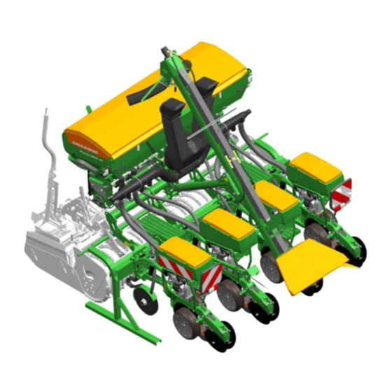
4 | Product description Product description CMS-T-00003748-E.1 4.1 Implement overview CMS-T-00003754-B.1 CMS-I-00002747 Fertiliser hopper Compressed air fan Lighting and identification for road travel Fertiliser filling auger Radar sensor Loading board Work lights MG6659-EN-GB | F.1 | 25.10.2022 | © AMAZONE... -
Page 27: Function Of The Implement
Depending on the requirements, the implement can be fitted with special equipment. Depending on the requirements, the implement can be fitted with special equipment. Alternatively, the fertiliser can also be carried in a front-mounted MG6659-EN-GB | F.1 | 25.10.2022 | © AMAZONE... -
Page 28: Special Equipment
Calibration kit 4.4 Protective equipment CMS-T-00003749-A.1 4.4.1 Fertiliser metering drive CMS-T-00002012-A.1 4.4.1.1 Guard screen locking mechanism CMS-T-00002016-A.1 To protect against injuries, the guard screens are equipped with locking mechanisms 1 . CMS-I-00001937 MG6659-EN-GB | F.1 | 25.10.2022 | © AMAZONE... -
Page 29: Warning Symbols
4 | Product description Warning symbols 4.4.1.2 Electric metering drive CMS-T-00002014-A.1 Drive guard Electric metering drive CMS-I-00001938 4.5 Warning symbols CMS-T-00003751-C.1 4.5.1 Position of the warning symbols CMS-T-00003752-A.1 CMS-I-00002926 MG6659-EN-GB | F.1 | 25.10.2022 | © AMAZONE... -
Page 30: Layout Of The Warning Symbols
Do not let anybody climb onto the driving implement. CMS-I-000081 4.6 Rating plate on the implement CMS-T-00004505-G.1 Implement number Vehicle ID number Product Permissible technical implement weight Model year Year of manufacture CMS-I-00004294 MG6659-EN-GB | F.1 | 25.10.2022 | © AMAZONE... -
Page 31: Compressed Air Fan
Each grain singling unit has its own seed hopper. The seed flows through the inlet opening in the grain singling unit. Seed hopper inlet Sliding shutter Air guiding element Opto-sensor Supply area Scraper CMS-I-00002295 MG6659-EN-GB | F.1 | 25.10.2022 | © AMAZONE... -
Page 32: Singling Disc
The singled seed grains are caught by the catch roller and pressed into the bottom of the furrow for good soil contact. The press rollers close the seed furrow. MG6659-EN-GB | F.1 | 25.10.2022 | © AMAZONE... -
Page 33: Depth Control Wheels
Depth control wheels with closed rim 1 have advantages with high amounts of organic residues. The scrapers 2 prevent soil from sticking and ensure that the seeding coulters run smoothly. CMS-I-00001954 MG6659-EN-GB | F.1 | 25.10.2022 | © AMAZONE... -
Page 34: Furrow Former And Catch Roller
The fertiliser hopper has large inspection windows at the front and rear to check the fill level. The rear fertiliser hopper can be safely reached via the loading board. MG6659-EN-GB | F.1 | 25.10.2022 | © AMAZONE... -
Page 35: Fertec Twin Coulter
The fertiliser placement depth is adjustable. The distance from the seeding coulter is determined by the coulter mount. The distance is of 60 mm. Cutting discs Fertiliser coulter pressure spring Coulter mount CMS-I-00001963 MG6659-EN-GB | F.1 | 25.10.2022 | © AMAZONE... -
Page 36: Filling Auger
Liquid fertiliser outlet CMS-I-00002728 4.12 Filling auger CMS-T-00001986-B.1 The filling auger facilitates the filling procedure for the fertiliser hopper. The filling auger is driven by the tractor's hydraulic system. Filling auger Filling funnel CMS-I-00001964 MG6659-EN-GB | F.1 | 25.10.2022 | © AMAZONE... -
Page 37: Micropellet Spreader
Sliding shutter Micropellet hopper Hopper cover CMS-I-00002590 PreTeC coulter with closer Application in the closing seed furrow, for slug pellet applications. Application in the seed furrow, for insecticide and micro-fertiliser applications. CMS-I-00003850 MG6659-EN-GB | F.1 | 25.10.2022 | © AMAZONE... -
Page 38: Lighting
4.14.1 Lighting and identification for road travel CMS-T-00005895-A.1 Lighting to the rear Warning signs Turn indicators Rear lights and brake lights Red reflectors Yellow reflector Lateral warning signs CMS-I-00001977 NOTE Depending on the national regulations. MG6659-EN-GB | F.1 | 25.10.2022 | © AMAZONE... -
Page 39: Work Lights
4.15.1 Radar sensor CMS-T-00001778-B.1 On electric drives, the radar sensor records the working speed. The working speed is used to determine the worked area and the required speed for the metering drives. CMS-I-00002221 MG6659-EN-GB | F.1 | 25.10.2022 | © AMAZONE... -
Page 40: Low Level Sensors
In conjunction with SmartControl, the scrapers are controlled automatically. By means of the opto-sensor monitoring, gaps or doubles are detected and the scraper bar position is adjusted. This automatically reduces gaps and doubles. CMS-I-00001917 MG6659-EN-GB | F.1 | 25.10.2022 | © AMAZONE... -
Page 41: Threaded Cartridge
CMS-T-00004156-B.1 With the TwinTerminal, the following functions can be executed: Calibrate the spread rate Emptying the implement Communication with the control terminal Enter the calibration parameters Enter the collected seed quantity CMS-I-00003079 MG6659-EN-GB | F.1 | 25.10.2022 | © AMAZONE... -
Page 42: Sealing Kit
Bridge plug for implement wiring harness CMS-I-00007071 Different row widths are required for seeding different different field crops. The parts listed below are required to convert the implement and to park the dismounted PreTeC mulch seeding coulters. MG6659-EN-GB | F.1 | 25.10.2022 | © AMAZONE... -
Page 43: Technical Data
Total length, depending on the equipment from the QuickLink mount 2.09 m 2.51 m Working width Centre of gravity distance, depending on the from the QuickLink mount 90 cm 90 cm equipment MG6659-EN-GB | F.1 | 25.10.2022 | © AMAZONE... -
Page 44: Permissible Total Weight
Drive Speed range Target spacing Electric drive 2 1/min to 55 1/min 3.8 cm to 86.9 cm Seed hopper 55 l/70 l MG6659-EN-GB | F.1 | 25.10.2022 | © AMAZONE... -
Page 45: Fertiliser Metering Unit
15 km/h. With an electric drive, the spread rate can be adjusted via the forward speed. Application Application point Maximum spread rate Micro-fertiliser Seed belt 35 kg/ha Micropellet hopper 17 l MG6659-EN-GB | F.1 | 25.10.2022 | © AMAZONE... -
Page 46: Coulters
Placement depth safety FerTeC Twin coulter Spring 80 kg 3 cm to 12 cm FerTeC Twin coulter, Is adjusted via the PreTeC mulch 200 kg 3 cm to 12 cm coupled seeding coulter. MG6659-EN-GB | F.1 | 25.10.2022 | © AMAZONE... -
Page 47: Row Spacings
5.10 Performance characteristics of the tractor CMS-T-00003766-C.1 Engine rating Precea 3000-A /-ACC above 117 kW kW / 160 PS Electrical system Battery voltage 12 V Basic tractor equipment for ISOBUS 25 A Lighting socket 7-pin MG6659-EN-GB | F.1 | 25.10.2022 | © AMAZONE... -
Page 48: Noise Development Data
On left in direction of travel 15 % On right in direction of travel 15 % Up the slope and down the slope Up the slope 15 % Down the slope 15 % MG6659-EN-GB | F.1 | 25.10.2022 | © AMAZONE... -
Page 49: Preparing The Machine
Total weight of front-mounted implement or front ballast Permissible total weight of rear-mounted implement or rear ballast Distance between the centre of gravity of the front-mounted implement or the front ballast and the centre of the front axle MG6659-EN-GB | F.1 | 25.10.2022 | © AMAZONE... - Page 50 T b 0,2 T b Vmin Vmin Vmin CMS-I-00000513 2. Calculate the actual front axle load. × × - × G a b T b G c + d Vtat Vtat Vtat CMS-I-00000516 MG6659-EN-GB | F.1 | 25.10.2022 | © AMAZONE...
- Page 51 Tyre load according to according to capacity for two tractor operating calculation tractor tyres manual ≤ Minimum front ballasting ≤ Total weight ≤ ≤ Front axle load ≤ ≤ Rear axle load MG6659-EN-GB | F.1 | 25.10.2022 | © AMAZONE...
-
Page 52: Coupling The Implement
Stickers are applied on the implement for the markings, which illustrate the respective hydraulic functions. The tractor control unit is used with different types of actuation, depending on the hydraulic function: CMS-I-00000121 MG6659-EN-GB | F.1 | 25.10.2022 | © AMAZONE... - Page 53 Risk of injury or even death If the hydraulic hose lines are incorrectly connected, the hydraulic functions may be faulty. When coupling the hydraulic hose lines, observe the coloured markings on the hydraulic plugs. MG6659-EN-GB | F.1 | 25.10.2022 | © AMAZONE...
-
Page 54: Coupling The Isobus Or Control Computer
1. Plug in the connector of the ISOBUS line 1 or the control computer line 2 . 2. Route the ISOBUS line with sufficient freedom of movement and without chafing or pinching points. CMS-I-00006891 MG6659-EN-GB | F.1 | 25.10.2022 | © AMAZONE... -
Page 55: Coupling The Power Supply
2-tube frame Wedge ring roller KW 3000-580-125 KW 3000-580-125 with 2-tube frame KW 3000-580-150 KW 3000-580-150 Wedge ring roller with matrix profile KWM 3000-600-125 KWM 3000-600-125 and 2-tube frame KWM 3000-600-150 KWM 3000-600-150 MG6659-EN-GB | F.1 | 25.10.2022 | © AMAZONE... - Page 56 The catching sockets 3 pick up the frame 4 . CMS-I-00002759 3. Install the coupling pieces 1 on both sides. CMS-I-00002753 4. Secure the coupling pieces 1 with the linch pins 2 on both sides. CMS-I-00002758 MG6659-EN-GB | F.1 | 25.10.2022 | © AMAZONE...
- Page 57 12. Remove the parking supports 2 from the implement 1 on both sides. CMS-I-00002760 13. Park the soil tillage implement with the coupled implement on a level surface. 14. The soil tillage implement is aligned horizontally. MG6659-EN-GB | F.1 | 25.10.2022 | © AMAZONE...
- Page 58 The horizontal adjustment of the soil tillage implement and the Precea are fundamental for uniform grain placement. To ensure uniform grain placement, CMS-I-00004121 check the grain placement after driving a short distance. MG6659-EN-GB | F.1 | 25.10.2022 | © AMAZONE...
-
Page 59: Operation Without Front Hopper
CMS-I-00002608 completely lift and lower the implement. To configure the working position sensor, refer to the ISOBUS software operating manual, "Configuring the working position sensor" see "control computer" operating manual. MG6659-EN-GB | F.1 | 25.10.2022 | © AMAZONE... -
Page 60: Filling The Seed Hopper
1. Open the fastener 2 . 2. Press the hopper cover 3 down. CMS-I-00001886 3. Unlock the 1 fastener. 4. Open the hopper cover 1 completely. The cover fastener 2 latches. 5. Fill the seed hopper. CMS-I-00001887 MG6659-EN-GB | F.1 | 25.10.2022 | © AMAZONE... -
Page 61: Filling The Fertiliser Hopper
4. When working at night, switch on the interior lighting of the fertiliser hopper. 5. Climb onto the loading board using the steps. To unfold the ladder, see "Operating the loading board with ladder". MG6659-EN-GB | F.1 | 25.10.2022 | © AMAZONE... - Page 62 2. Open the cover tarpaulin 1 of the filling funnel. 3. Swivel out the filling chute 2 . 4. Remove residues or foreign objects from the filling funnel. CMS-I-00001894 MG6659-EN-GB | F.1 | 25.10.2022 | © AMAZONE...
- Page 63 10. Switch off the "beige" tractor control unit. 11. Swivel in the filling chute. 12. Close the cover tarpaulin of the filling funnel. MG6659-EN-GB | F.1 | 25.10.2022 | © AMAZONE...
-
Page 64: Preparing The Micropellet Spreader For Operation
1. Open the fastener 2 . 2. Press the hopper cover 3 down. CMS-I-00002595 3. Unlock the 1 fastener. 4. Open the hopper cover 1 . 5. Fill the micropellet hopper. CMS-I-00002598 MG6659-EN-GB | F.1 | 25.10.2022 | © AMAZONE... - Page 65 2. Insert the unlocking tool 2 into the metering unit cover 1 . 3. Unlock the metering unit cover on the metering housing 3 . 4. Open the metering unit cover. CMS-I-00002582 MG6659-EN-GB | F.1 | 25.10.2022 | © AMAZONE...
- Page 66 2 kg/ha to wheel Silver grey Slug pellets 10 kg/ha 3 cm³ Metering Micro- 10 kg/ha to wheel Green fertiliser 35 kg/ha 12 cm³ 10. Insert the desired metering roller into the roller cage. MG6659-EN-GB | F.1 | 25.10.2022 | © AMAZONE...
- Page 67 6.3.4.3 Changing the application point CMS-T-00003633-C.1 PreTeC mulch seeding coulter with closer Application in the closing seed furrow, optionally with targeted outlet or diffuser. Application in the seed furrow, optionally with targeted outlet or diffuser. CMS-I-00002579 MG6659-EN-GB | F.1 | 25.10.2022 | © AMAZONE...
- Page 68 2. Move the diffuser 2 to the desired position. If the desired position cannot be set, Loosen the bolts 3 . 3. Move the diffuser to the desired position. 4. Tighten the bolts. CMS-I-00002837 MG6659-EN-GB | F.1 | 25.10.2022 | © AMAZONE...
-
Page 69: Determining The Setting Parameters
Green 16 mm 16 mm 16 mm 16 mm 5 mbar Squas Opal 45 mbar ± 4 mm F / G Green 20 mm 20 mm 20 mm 16 mm green 5 mbar MG6659-EN-GB | F.1 | 25.10.2022 | © AMAZONE... -
Page 70: Adjusting The Fan Speed Via The Hydraulic System
The seed hoppers are filled The implement is unfolded The fan is switched on The singling discs are filled with seed grains The fan speed changes until the hydraulic fluid has reached its operating temperature. MG6659-EN-GB | F.1 | 25.10.2022 | © AMAZONE... - Page 71 Read the fan pressure on the pressure gauge. NOTE If the desired fan pressure is not reached, a bigger hydraulic motor can help. For more information, contact your specialist workshop. MG6659-EN-GB | F.1 | 25.10.2022 | © AMAZONE...
-
Page 72: Setting Up The Speed Sensor On The Implement
Determine the grain size of the seed with the multi- placement tester. 1. Put the seed in the reference holes 1 . If the seed lies loosely on the reference hole, read the hole diameter. CMS-I-00001217 MG6659-EN-GB | F.1 | 25.10.2022 | © AMAZONE... - Page 73 3. Expose 11 grains in one row. 4. Place the multi-placement tester horizontally on the ground. 5. Measure 10 grain spacings with the ruler 1 . 6. Calculate the average grain spacing. ® Ab10 Ab10 Ab1-10 Ab1-10 CMS-I-00002066 MG6659-EN-GB | F.1 | 25.10.2022 | © AMAZONE...
-
Page 74: Adjusting The Grain Singling Unit
6.3.9 Adjusting the grain singling unit CMS-T-00005516-D.1 6.3.9.1 Changing the singling disc CMS-T-00005572-C.1 1. Secure the tractor and implement. 2. Open the locks 1 . 3. Remove the cover 2 . CMS-I-00001909 MG6659-EN-GB | F.1 | 25.10.2022 | © AMAZONE... - Page 75 Remove the bolt 4 . 7. Install the orange filling block 3 in the mount 8. Install the bolt. CMS-I-00003937 9. For use in rapeseed, beets, or sorghum, remove the cap 1 . MG6659-EN-GB | F.1 | 25.10.2022 | © AMAZONE...
- Page 76 The points 1 and 3 are no longer aligned. CMS-I-00001911 NOTE The sealing wax dot 1 indicates a factory setting. 16. Check the sealing wax dot. If the sealing wax dot has been broken, contact your specialist workshop. CMS-I-00005636 MG6659-EN-GB | F.1 | 25.10.2022 | © AMAZONE...
- Page 77 23. Install the narrow hole covering roller 2 . 24. Put on the nut. CMS-I-00003868 25. Align the guide pin 1 . 26. Close the cover 2 . 27. Close the locks. CMS-I-00001913 MG6659-EN-GB | F.1 | 25.10.2022 | © AMAZONE...
- Page 78 D / E G / H E / F / G B / C E / F / G F / G position 1. Move the sliding shutter 1 to the desired position. CMS-I-00001915 MG6659-EN-GB | F.1 | 25.10.2022 | © AMAZONE...
- Page 79 6.3.9.3 Changing the opto-sensor and shot channel CMS-T-00005387-B.1 NOTE The opto-sensor must be adapted to the respective operating conditions. 1. Uncouple the ISOBUS line. 2. Remove the spring cotter pin 1 . CMS-I-00003814 MG6659-EN-GB | F.1 | 25.10.2022 | © AMAZONE...
- Page 80 5. Remove the bolts 1 . 6. Remove the spacer plate 2 . CMS-I-00003816 7. Disconnect the plug connection 3 . 8. Move the opto-sensor 1 down. 9. Remove the gasket 2 . CMS-I-00003817 MG6659-EN-GB | F.1 | 25.10.2022 | © AMAZONE...
- Page 81 "Determining the setting parameters". 12. Install the desired opto-sensor 1 . CMS-I-00002826 13. Move the opto-sensor 1 up. 14. Put on the gasket 2 . 15. Establish the plug connection 3 . CMS-I-00003817 MG6659-EN-GB | F.1 | 25.10.2022 | © AMAZONE...
- Page 82 23. Restart the implement. CMS-I-00003814 6.3.9.4 Adjusting the scraper mechanically CMS-T-00001896-C.1 NOTE The adjustment of the scraper must be adapted to the respective operating conditions. The optimum adjustment can only be determined during field operation. MG6659-EN-GB | F.1 | 25.10.2022 | © AMAZONE...
-
Page 83: Changing The Seed Spread Rate
4. Check the adjustment of the scraper on the field after driving a short distance. 6.3.10 Changing the seed spread rate CMS-T-00003742-D.1 6.3.10.1 Manually calculating the grain spacing CMS-T-00003838-C.1 Formula symbol Designation Grains G/ha Spread rate per hectare Row width m MG6659-EN-GB | F.1 | 25.10.2022 | © AMAZONE... - Page 84 See "Changing the seed spread rate" in the ISOBUS operating manual 6.3.10.2.2 Determining the working speed CMS-T-00002251-G.1 NOTE The specified values are reference values. They are based on a constant power supply of at least 12 volt. MG6659-EN-GB | F.1 | 25.10.2022 | © AMAZONE...
- Page 85 15 km/h 15 km/h 12.8 km/h 12 km/h 14 k/m² 15 km/h 15 km/h 14.9 km/h 11.9 km/h 11.1 km/h 15 k/m² 15 km/h 15 km/h 13.9 km/h 11.1 km/h 10.4 km/h MG6659-EN-GB | F.1 | 25.10.2022 | © AMAZONE...
- Page 86 7 km/h 5.8 km/h 4.7 km/h 4.4 km/h 72 k/m² 7.3 km/h 6.6 km/h 5.5 km/h 4.4 km/h 4.1 km/h 76 k/m² 6.9 km/h 6.3 km/h 5.2 km/h 4.2 km/h 3.9 km/h MG6659-EN-GB | F.1 | 25.10.2022 | © AMAZONE...
-
Page 87: Adjusting The Pretec Mulch
The star clearers should only move plant residues to the side. If the soil is moved completely, the press roller does not have enough fine soil to close the seed furrow. MG6659-EN-GB | F.1 | 25.10.2022 | © AMAZONE... - Page 88 If the soil is moved completely by the clod clearer or the clod clearer tip, the press roller does not have enough fine soil to close the seed furrow. MG6659-EN-GB | F.1 | 25.10.2022 | © AMAZONE...
- Page 89 The rigid cutting discs allow the seeding unit to run smoothly on soils with coarse surface structures. The rigid cutting discs cut through plant residues and clear the area of the seeding coulter. MG6659-EN-GB | F.1 | 25.10.2022 | © AMAZONE...
- Page 90 6.3.11.4 Adjusting the seed placement depth CMS-T-00005825-C.1 NOTE The adjustment of the seed placement depth must be adapted to the respective operating conditions. The optimum adjustment can only be determined during field operation. MG6659-EN-GB | F.1 | 25.10.2022 | © AMAZONE...
- Page 91 A . 6. Lock the setting lever in the grid. To check the setting, drive for 30 m at working speed and "check the seed placement depth". MG6659-EN-GB | F.1 | 25.10.2022 | © AMAZONE...
- Page 92 ISOBUS operating manual "Adjusting the coulter pressure". To check the setting, drive for 30 m at working speed and "check the seed placement depth". MG6659-EN-GB | F.1 | 25.10.2022 | © AMAZONE...
- Page 93 CMS-T-00001932-E.1 Disc closer Disc closer setting lever CMS-I-00001962 The disc closers are used on ploughed or mulched soils. They cover the seed furrow with fine soil. The disc closer pressure is adjustable. MG6659-EN-GB | F.1 | 25.10.2022 | © AMAZONE...
- Page 94 Move the disc closers in the tracks to the desired position. 6. Lock the setting lever in the grid. CMS-I-00001926 To check the setting, drive for 30 m at working speed and then check the work pattern. MG6659-EN-GB | F.1 | 25.10.2022 | © AMAZONE...
- Page 95 Increase the press roller Heavy soils pressure: + Reduce the press roller Light soils pressure: - CMS-I-00002743 1. Lift the implement. 2. Secure the tractor and implement. 3. Unlock the setting lever 1 . MG6659-EN-GB | F.1 | 25.10.2022 | © AMAZONE...
- Page 96 13. Remove the bolt 1 with the press roller. 14. Move the press roller 3 with the setting bushing 2 to the desired position. 15. Install the press roller with bolts. 16. Tighten the lock nut. MG6659-EN-GB | F.1 | 25.10.2022 | © AMAZONE...
- Page 97 "Changing the catch roller". 6.3.11.10 Adjusting the depth control wheel scraper CMS-T-00001936-E.1 IMPORTANT Damage to the depth control wheel due to abrasion by the scraper To check the distance, rotate the depth control wheel MG6659-EN-GB | F.1 | 25.10.2022 | © AMAZONE...
- Page 98 CMS-I-00002700 2. Put a suitable support 1 under the coulter. To move the locking mechanism to the locking position, slowly lower the implement. The coulter is fixed in the parking position. CMS-I-00002706 MG6659-EN-GB | F.1 | 25.10.2022 | © AMAZONE...
- Page 99 The coulter is lowered into working position. CMS-I-00002699 6.3.11.12 Adjusting the catch roller scraper CMS-T-00003720-D.1 IMPORTANT Damage to the depth control wheel due to abrasion by the scraper To check the distance, rotate the depth control wheel MG6659-EN-GB | F.1 | 25.10.2022 | © AMAZONE...
- Page 100 To select the catch roller, CMS-I-00002876 see "Determining the setting parameters". 8. Install the desired catch roller. To install the suitable furrow former for the catch roller, see "Changing the furrow former". MG6659-EN-GB | F.1 | 25.10.2022 | © AMAZONE...
-
Page 101: Creating Tramlines
To take the calibration buckets out of CMS-I-00001932 the parking position on implements with mechanical fan drive, pull out the calibration buckets individually to the side on the left and right. MG6659-EN-GB | F.1 | 25.10.2022 | © AMAZONE... - Page 102 To enter the spread rate for the fertiliser on the control terminal, refer to the ISOBUS software operating manual, CMS-I-00001956 "Calibrating the spread rate for fertiliser or micropellets". NOTE To prevent overflowing of the calibration bucket, monitor the fill level. MG6659-EN-GB | F.1 | 25.10.2022 | © AMAZONE...
- Page 103 8 km/h 6.7 km/h 5.3 km/h 5 km/h 700 kg/ha 8.4 km/h 7.5 km/h 6 km/h 5 km/h 4.7 km/h 740 kg/ha 7.9 km/h 7.1 km/h 5.9 km/h 4.8 km/h 4.5 km/h MG6659-EN-GB | F.1 | 25.10.2022 | © AMAZONE...
- Page 104 5.2 kg/ha 4.3 kg/ha 3.5 kg/ha 3.2 kg/ha 740 kg/ha 5.5 kg/ha 4.9 kg/ha 4.1 kg/ha 3.3 kg/ha 3.1 kg/ha 780 kg/ha 5.2 kg/ha 4.7 kg/ha 3.9 kg/ha 3.1 kg/ha 2.9 kg/ha MG6659-EN-GB | F.1 | 25.10.2022 | © AMAZONE...
-
Page 105: Changing The Application Rate For Liquid Fertiliser
A = Rate in kg/ha v = Forward speed in km/h = Row width in m ´ ´ 15 0 75 2 89 2. Determine the flow rate with the equation. ´ ´ CMS-I-00002733 MG6659-EN-GB | F.1 | 25.10.2022 | © AMAZONE... - Page 106 The determined values are reference values. Check the setting each time the applied CMS-I-00002735 material is changed. During application in the seed furrow, liquid fertiliser can drip out of the application point in the headland position. MG6659-EN-GB | F.1 | 25.10.2022 | © AMAZONE...
-
Page 107: Adjusting The Placement Depth On The Coupled Fertiliser Coulter
Check the adjustment of the fertiliser coulter on the field after driving a short distance. The bolt 2 serves for orientation on the scale 1 . CMS-I-00002042 MG6659-EN-GB | F.1 | 25.10.2022 | © AMAZONE... -
Page 108: Adjusting The Fertiliser Application Point
6.3.17 Adjusting the fertiliser application point CMS-T-00010605-B.1 Use the switch 3 to change the fertiliser application point between the fertiliser coulter 2 or the seed bed placement 1 . CMS-I-00007256 MG6659-EN-GB | F.1 | 25.10.2022 | © AMAZONE... -
Page 109: Adjusting The Filling Auger
Loosen the bolt 2 . 2. Loosen the bolt 1 and remove it. CMS-I-00002029 3. Move the outlet to the desired position. 4. Insert the bolt 1 and tighten it. 5. Tighten the bolt 2 . MG6659-EN-GB | F.1 | 25.10.2022 | © AMAZONE... -
Page 110: Using The Loading Board
8. The setting lever must lock in the setting grid. 6.3.19 Using the loading board CMS-T-00003737-B.1 1. Remove the safety cotter pin 1 . CMS-I-00002744 2. Pull out the ladder 1 and swivel it down. CMS-I-00002836 MG6659-EN-GB | F.1 | 25.10.2022 | © AMAZONE... -
Page 111: Adjusting The Coulter Pressure In The Track
When the coulter pressure beside the tracks is adjusted, the coulter pressure in the tracks is increased by the set value. To check the setting after driving a short distance: See "Checking the placement depth". MG6659-EN-GB | F.1 | 25.10.2022 | © AMAZONE... -
Page 112: Installing A Seed Row
2 . 6. Fasten 2 load handling devices on the coulter body 1 . CMS-I-00004137 7. Guide the tilted coulter 1 along the frame 2 . 8. Lower the coulter. CMS-I-00004136 MG6659-EN-GB | F.1 | 25.10.2022 | © AMAZONE... - Page 113 "Coupling the air and fertiliser supply". To put the desired coulter into operation, see "Coupling the energy supply". If the implement is equipped with a hydraulic coulter pressure system, see "Coupling the hydraulic supply". MG6659-EN-GB | F.1 | 25.10.2022 | © AMAZONE...
- Page 114 3. Lower the implement and move the three-point hydraulic system of tractor into float position. The coulter pressure cylinders retract and the coulter pressure is relieved. CMS-I-00007310 4. Switch off the fan. 5. Secure the tractor and implement. MG6659-EN-GB | F.1 | 25.10.2022 | © AMAZONE...
- Page 115 14. Disconnect the connection 3 . 15. Remove the long hydraulic hose 1 . CMS-I-00007202 16. Install the original hydraulic hose between the coulters. To replace the second line repeat steps 1 to 3. MG6659-EN-GB | F.1 | 25.10.2022 | © AMAZONE...
- Page 116 When the hydraulic coulter pressure system has been vented, close the valve 3 . 23. Install the fastener 1 . 24. Install the bolt 2 . MG6659-EN-GB | F.1 | 25.10.2022 | © AMAZONE...
- Page 117 6.3.21.5 Establishing the air and fertiliser supply on the distributor head CMS-T-00005489-D.1 To restore the fertiliser flow on implements with distributor heads: actuate the lever 1 . The fertiliser is conveyed into the fertiliser coulter. CMS-I-00003960 MG6659-EN-GB | F.1 | 25.10.2022 | © AMAZONE...
- Page 118 5. Seal the free connection cable with a dust cap after the row conversion. 6. Install the conveyor hose 1 on the fertiliser coulter 3 . 7. Install the clamp 2 . CMS-I-00003920 MG6659-EN-GB | F.1 | 25.10.2022 | © AMAZONE...
-
Page 119: Removing Seed Rows
The contact force sensor can be recognised by the signal processing 2 . CMS-I-00003921 Conversion Removing recommendation From 6 to 4 rows Rows 2 and 5 From 12 to 8 rows Rows 3, 5, 8 and 10 MG6659-EN-GB | F.1 | 25.10.2022 | © AMAZONE... - Page 120 3. Lower the implement and move the three-point hydraulic system of tractor into float position. The coulter pressure cylinders retract and the coulter pressure is relieved. CMS-I-00007310 4. Switch off the fan. MG6659-EN-GB | F.1 | 25.10.2022 | © AMAZONE...
- Page 121 13. Install connectors 5 between the hydraulic hoses. CMS-I-00007201 14. Install sealing caps 1 from the sealing kit on the T-piece 2 . To convert the hydraulic supply of the second line repeat steps 1 to 3. MG6659-EN-GB | F.1 | 25.10.2022 | © AMAZONE...
- Page 122 When the hydraulic coulter pressure system has been vented, close the valve 3 . 24. Install the fastener 1 . 25. Install the bolt 2 . MG6659-EN-GB | F.1 | 25.10.2022 | © AMAZONE...
- Page 123 To interrupt the fertiliser flow on implements with distributor heads: actuate the lever 1 . The fertiliser is then conveyed back into the corrugated tube and the conveyor air is diverted close to the ground. CMS-I-00003959 MG6659-EN-GB | F.1 | 25.10.2022 | © AMAZONE...
- Page 124 For a conversion from 12 to 8 rows connect the setting motors for rows 3 to 12 to the wiring harness according to the table. 6. Seal the free connection cable with a dust cap. MG6659-EN-GB | F.1 | 25.10.2022 | © AMAZONE...
- Page 125 6.3.22.6 Removing the PreTeC mulch seeding coulter CMS-T-00005475-C.1 REQUIREMENTS Energy supply disconnected Hydraulic supply disconnected Air and fertiliser supply disconnected 1. Remove the bolts 1 . 2. Remove the coulter bracket 2 . CMS-I-00004135 MG6659-EN-GB | F.1 | 25.10.2022 | © AMAZONE...
- Page 126 "Adjusting the seed placement depth" CMS-I-00005134 To move the catch roller to position see "Adjusting the catch roller" 12. Lift the implement. 13. Position the transport dolly 2 under the coulter to be removed. MG6659-EN-GB | F.1 | 25.10.2022 | © AMAZONE...
- Page 127 21. Push the coulters into the desired position. For telescopic coulters Tighten the bolts to 160 Nm minus 180°, For non-telescopic coulters CMS-I-00002039 Tighten the bolts to 200 Nm. 23. Connect the ISOBUS to the tractor. MG6659-EN-GB | F.1 | 25.10.2022 | © AMAZONE...
-
Page 128: Preparing The Machine For Road Travel
2 of the trailing roller in a folded state. 4. Before driving off, check that the roller transport lock is engaged. If the roller transport lock is not engaged, move the roller outwards until the roller transport lock engages. CMS-I-00002932 MG6659-EN-GB | F.1 | 25.10.2022 | © AMAZONE... -
Page 129: Increasing The Mechanical Coulter Pressure
To put the coulter pressure to the middle position, see "Adjusting the coulter pressure mechanically". 6.4.3 Locking the tractor control units CMS-T-00006337-C.1 Depending on the equipment, the tractor control units are locked mechanically or electrically. MG6659-EN-GB | F.1 | 25.10.2022 | © AMAZONE... -
Page 130: Using The Machine
The speed of the singling discs is immediately adjusted to normal changes in speed. To check the seed placement depth and grain spacing after the first 30 m, see "Checking the seed placement depth" and "Checking the grain spacing". MG6659-EN-GB | F.1 | 25.10.2022 | © AMAZONE... -
Page 131: Turning On The Headlands
The fan is running WARNING Specific coulters are hydraulically shifted The shifting procedure cannot be stopped. Only a bit of space remains between the coulters. Keep people out of the danger area of the implement. MG6659-EN-GB | F.1 | 25.10.2022 | © AMAZONE... - Page 132 "Configuring the tramline control". To shift the coulters, drive into the upcoming tramline with the implement lifted. If the coulters have not reached the end position, slowly drive up with the implement lowered. MG6659-EN-GB | F.1 | 25.10.2022 | © AMAZONE...
-
Page 133: Eliminating Faults
Speed fluctuations occur on the Contact your specialist drive. hydraulic drive. workshop. The fill level in the singling unit The brushes of the filling block are see page 132 housing is too high. worn. MG6659-EN-GB | F.1 | 25.10.2022 | © AMAZONE... - Page 134 8 | Eliminating faults Errors Cause Solution To replace the furrow former, The seed furrow is unstable or The furrow former is worn. does not maintain its shape. see "Changing the furrow former". MG6659-EN-GB | F.1 | 25.10.2022 | © AMAZONE...
- Page 135 2 , it is not reliably caught. The position of the catch roller can be adjusted. The position of the catch roller must be adjusted by trained specialist personnel. Contact your specialist workshop. CMS-I-00001925 MG6659-EN-GB | F.1 | 25.10.2022 | © AMAZONE...
- Page 136 To increase the throughput on the press rollers, install the press roller with offset. CMS-I-00002041 4. Install the press roller with the bolt 2 in the hole 5. Put on the nut and tighten it. MG6659-EN-GB | F.1 | 25.10.2022 | © AMAZONE...
- Page 137 If the predominant operating conditions do not allow for continuous operation of the implement, replace the depth control wheels with open rim with depth control wheels with closed rim. Stopping of several singling discs CMS-T-00003760-B.1 CMS-I-00002695 MG6659-EN-GB | F.1 | 25.10.2022 | © AMAZONE...
- Page 138 If the brushes of the filling block are worn, the seed does not flow back into the storage area 2 within the filling block. To replace the defective filling block, see "Changing the singling disc" contact your specialist workshop. CMS-I-00005635 MG6659-EN-GB | F.1 | 25.10.2022 | © AMAZONE...
-
Page 139: Parking The Machine
The implement is coupled to the tractor The tractor and implement are secured NOTE The parking position for the chute is in the hopper cover for row 1. 1. Take out the chute 1 . CMS-I-00001888 MG6659-EN-GB | F.1 | 25.10.2022 | © AMAZONE... -
Page 140: Emptying The Seed Hopper Through The Singling Disc
The implement is coupled to the tractor The tractor and implement are secured NOTE The parking position for the chute is in the hopper cover for row 1. 1. Take out the chute 1 . CMS-I-00001888 MG6659-EN-GB | F.1 | 25.10.2022 | © AMAZONE... - Page 141 5. Put the collection bucket 2 under the chute. CMS-I-00001997 Hook the collection bucket 2 onto the chute. 6. Put the collection bucket 2 under the chute. 7. Release the lock 1 until the points 2 are aligned. CMS-I-00001910 MG6659-EN-GB | F.1 | 25.10.2022 | © AMAZONE...
- Page 142 11. Turn the lock 1 beyond the notch 2 . The points 3 are no longer aligned. CMS-I-00001911 12. Close the cover 2 . NOTE Pay attention to the guide pin 1 . 13. Close the locks. CMS-I-00001913 MG6659-EN-GB | F.1 | 25.10.2022 | © AMAZONE...
-
Page 143: Emptying The Fertiliser Metering Unit
2 . To move the bottom flap lever to the emptying position, press and hold the lock button 3 and push it down 4 . 8. Take out the residual quantity. CMS-I-00001994 MG6659-EN-GB | F.1 | 25.10.2022 | © AMAZONE... -
Page 144: Emptying The Micropellet Hopper
9.5 Emptying the micropellet hopper CMS-T-00003603-A.1 1. Close the the sliding shutter 1 on the micropellet hopper. CMS-I-00002586 2. Move the switchover flap 1 to position A . CMS-I-00002580 MG6659-EN-GB | F.1 | 25.10.2022 | © AMAZONE... - Page 145 The micropellets are collected in the collapsible bucket. CMS-I-00002576 When the residual quantity has be fully collected, move the bottom flap lever 1 back into working position. 7. Open the sliding shutter 2 completely. CMS-I-00002622 MG6659-EN-GB | F.1 | 25.10.2022 | © AMAZONE...
-
Page 146: Relieving The Hole Covering Rollers
The implement is coupled to the tractor The tractor and implement are secured 1. Open the locks 1 . 2. Remove the cover 2 . CMS-I-00001909 3. Release the lock 1 until the points 2 are aligned. CMS-I-00001910 MG6659-EN-GB | F.1 | 25.10.2022 | © AMAZONE... -
Page 147: Parking The Pretec Coulter
Pay attention to the guide pin 1 . 7. Close the locks. CMS-I-00001913 9.7 Parking the PreTeC coulter CMS-T-00001920-D.1 In the P position, the lowered depth control wheels protect the furrow formers 1 and catch roller 2 . CMS-I-00001999 MG6659-EN-GB | F.1 | 25.10.2022 | © AMAZONE... -
Page 148: Disconnecting The Supply Lines From The Front-Mounted Hopper
3. Depending on the implement equipment, disconnect the front hopper supply 3 from the hose package. 4. Depending on the implement equipment, CMS-I-00003124 disconnect the metering unit shutoff 4 from the hose package. MG6659-EN-GB | F.1 | 25.10.2022 | © AMAZONE... -
Page 149: Disconnecting The Supply Lines From The Front Hopper
1. Secure the tractor and implement. 2. Put the control lever on the tractor control unit in float position. 3. Disconnect the hydraulic hose lines 1 . 4. Put the dust caps on the hydraulic sockets. CMS-I-00001065 MG6659-EN-GB | F.1 | 25.10.2022 | © AMAZONE... -
Page 150: Uncoupling The Power Supply
5. Hang the hydraulic hose lines 1 in the hose cabinet. CMS-I-00001250 9.12 Uncoupling the power supply CMS-T-00001402-G.1 1. Pull out the plug 1 for the power supply. CMS-I-00001048 2. Hang the plugs 1 in the hose cabinet. CMS-I-00001248 MG6659-EN-GB | F.1 | 25.10.2022 | © AMAZONE... -
Page 151: Uncoupling The Quicklink
7. Remove the top link pin 1 on the soil tillage implement. 8. Remove the top link 2 . CMS-I-00002752 9. Remove the linch pins 1 from the coupling pieces 2 on both sides. CMS-I-00002758 MG6659-EN-GB | F.1 | 25.10.2022 | © AMAZONE... - Page 152 12. Slowly drive the tractor forwards with the coupled soil tillage implement. 13. Install the coupling pieces 1 on both sides. 14. Secure the coupling pieces 1 with the linch pins 2 on both sides. CMS-I-00002762 MG6659-EN-GB | F.1 | 25.10.2022 | © AMAZONE...
-
Page 153: Parking The Seeding Combination
Risk of injury or even death due to tipping over of the seeding combination CMS-I-00001249 Since the parking supports are not designed for the coupled seeding combination, do not park the seeding combination on the parking supports. MG6659-EN-GB | F.1 | 25.10.2022 | © AMAZONE... - Page 154 80 mm x 80 mm in front of and behind the roller of the soil tillage implement. 5. Uncouple the lower links 2 from the implement from the tractor seat. 6. Drive the tractor forward. MG6659-EN-GB | F.1 | 25.10.2022 | © AMAZONE...
-
Page 155: Repairing The Machine
164 Cleaning the micropellet metering unit see page 165 Clean the singling unit see page 168 Every 50 operating hours / weekly Checking the hydraulic hose lines see page 158 MG6659-EN-GB | F.1 | 25.10.2022 | © AMAZONE... - Page 156 Every 100 operating hours / Every 12 months Cleaning the filling auger see page 161 Cleaning the fertiliser hopper see page 162 Adjusting the micropellet metering unit bottom flap see page 167 MG6659-EN-GB | F.1 | 25.10.2022 | © AMAZONE...
-
Page 157: Checking And Replacing The Cutting Discs On The Pretec Mulch Seeding Coulter
12. Install spacer discs that are not required on the opposite side of the cutting disc bearing with the central bolt. 13. Put on and tighten the central bolt. 14. Install the dust caps. MG6659-EN-GB | F.1 | 25.10.2022 | © AMAZONE... -
Page 158: Adjusting The Cutting Disc Distance On The Pretec Mulch Seeding Coulter
6. Put on and tighten the central bolt. 7. Install the dust caps. 8. Install the depth control wheel along with the bracket. MG6659-EN-GB | F.1 | 25.10.2022 | © AMAZONE... -
Page 159: Adjusting The Cutting Disc Drive On The Pretec Mulch Seeding Coulter
3. Loosen and remove the bolts 2 . 4. Replace worn closer discs 1 with new closer discs. 5. Put on and tighten the bolts. CMS-I-00005666 MG6659-EN-GB | F.1 | 25.10.2022 | © AMAZONE... -
Page 160: Checking And Replacing The Rigid Cutting Disc On The Pretec Mulch Seeding Coulter
The right central bolt has right-hand thread The left central bolt has left-hand thread 5. Remove the worn cutting disc 2 . 6. Unscrew and remove the bolts on the bearing seat 1 . MG6659-EN-GB | F.1 | 25.10.2022 | © AMAZONE... -
Page 161: Adjusting The Cutting Disc Distance On The Fertec Twin Coulter
CMS-I-00002019 slightly, remove or add spacer discs 4 as required. 4. Install spacer discs that are not required on the opposite side of the cutting disc bearing with the central bolt. MG6659-EN-GB | F.1 | 25.10.2022 | © AMAZONE... -
Page 162: Checking And Replacing The Inner Scraper On The Fertec Twin Coulter
4. Pay attention to the number of spacer discs 4 . 5. Replace inner scrapers 5 if worn. 6. Install the cutting discs. 7. Put on and tighten the central bolt. 8. Install the dust caps. MG6659-EN-GB | F.1 | 25.10.2022 | © AMAZONE... -
Page 163: Checking The Tightening Torque For The Radar Sensor Bolts
On telescopic coulters Tighten the bolts to 160 Nm -180° On non-telescopic coulters Tighten the bolts to 200 Nm. NOTE The tightening torques must be checked when the coulters are unloaded. CMS-I-00002039 MG6659-EN-GB | F.1 | 25.10.2022 | © AMAZONE... -
Page 164: Checking The Top Link Pin And Lower Link Pin
Hydraulic hose lines must not be more than 6 years old. 3. Check the manufacturing date 1 . CMS-I-00000532 4. Have any worn, damaged or aged hydraulic hose lines immediately replaced at a specialist workshop. 5. Retighten loose bolted connections. MG6659-EN-GB | F.1 | 25.10.2022 | © AMAZONE... -
Page 165: Cleaning The Fan Rotor
When most of the water has escaped through the air distributor, run the fan for about 5 minutes. The air supply is blown dry. 4. Switch off the fan. CMS-I-00002024 5. Close the water drain on the air distributor. MG6659-EN-GB | F.1 | 25.10.2022 | © AMAZONE... -
Page 166: Cleaning The Cyclone Separator
5. Install the cover with the wing nut. CMS-I-00002765 6. Fasten the suction cage with the clips. 10.1.16 Cleaning the suction basket CMS-T-00003836-A.1 INTERVAL Every 10 operating hours daily Clean the suction baskets 1 . CMS-I-00002793 MG6659-EN-GB | F.1 | 25.10.2022 | © AMAZONE... -
Page 167: Cleaning The Filling Auger
7. Thoroughly clean the filling auger 3 with a water jet. 8. Put on the installation flap. 9. Put on the bolts and tighten them. 10. Install the cover. CMS-I-00002027 11. Put on the nuts and tighten them. MG6659-EN-GB | F.1 | 25.10.2022 | © AMAZONE... -
Page 168: Cleaning The Fertiliser Hopper
2 . 9. Remove residues or foreign objects from the fertiliser hopper. 10. Close the protective screen. 11. Park the unlocking tool on the fertiliser hopper. CMS-I-00002028 MG6659-EN-GB | F.1 | 25.10.2022 | © AMAZONE... - Page 169 To move the calibration flap lever into working position, press and hold the lock button and push it upwards. To move the bottom flap lever into working position, press and hold the lock button and push it CMS-I-00001932 upwards. MG6659-EN-GB | F.1 | 25.10.2022 | © AMAZONE...
-
Page 170: Cleaning The Fertiliser Metering Unit
5. Remove residues or foreign objects from the metering housing. 6. Close the metering unit cover 3 . 7. Park the unlocking tool from the threaded cartridge or the parking position in the fertiliser hopper. MG6659-EN-GB | F.1 | 25.10.2022 | © AMAZONE... -
Page 171: Cleaning The Micropellet Metering Unit
4. Insert the unlocking tool 2 into the metering unit cover 1 . 5. Unlock the metering unit cover on the metering housing 3 . 6. Open the metering unit cover. CMS-I-00002582 MG6659-EN-GB | F.1 | 25.10.2022 | © AMAZONE... - Page 172 CMS-I-00002584 10. Clean the metering housing 11. Actuate the switchover flap 4 several times. 12. Actuate the bottom flap lever 1 several times. 13. Clean the outlets 2 and 3 . CMS-I-00002577 MG6659-EN-GB | F.1 | 25.10.2022 | © AMAZONE...
-
Page 173: Adjusting The Micropellet Metering Unit Bottom Flap
Every 12 months 1. Move the bottom flap lever 3 into working position. To adjust the pre-tension, the bolt head 1 should be 9 -10 mm above the clamping lever 2 . CMS-I-00002581 MG6659-EN-GB | F.1 | 25.10.2022 | © AMAZONE... -
Page 174: Clean The Singling Unit
4. Release the lock 1 until the points 2 are aligned. CMS-I-00001910 5. remove the singling disc 1 from the drive hub. 6. Clean the singling unit housing. 7. Install the singling disc. CMS-I-00001912 MG6659-EN-GB | F.1 | 25.10.2022 | © AMAZONE... -
Page 175: Cleaning The Opto-Sensor
10.1.23 Cleaning the opto-sensor CMS-T-00002393-C.1 INTERVAL Every 50 operating hours as required 1. Disconnect the ISOBUS connection to the tractor. 2. Open the locks 1 . 3. Remove the cover 2 . CMS-I-00001909 MG6659-EN-GB | F.1 | 25.10.2022 | © AMAZONE... - Page 176 7. Rinse the opto-sensor with clear fresh water. 8. Install the singling disc. 9. Install the cover. To remove stubborn contamination, remove the opto-sensor. Remove the spring cotter pin 1 . CMS-I-00003814 MG6659-EN-GB | F.1 | 25.10.2022 | © AMAZONE...
- Page 177 13. Remove the bolts 1 . 14. Remove the spacer plate 2 . CMS-I-00003816 15. Disconnect the plug connection 3 . 16. Move the opto-sensor 1 down. 17. Remove the gasket 2 . CMS-I-00003817 MG6659-EN-GB | F.1 | 25.10.2022 | © AMAZONE...
- Page 178 21. Rinse the opto-sensor with clear fresh water. 22. Insert the opto-sensor 1 . CMS-I-00002826 23. Move the opto-sensor 1 up. 24. Put on the gasket 2 . 25. Establish the plug connection 3 . CMS-I-00003817 MG6659-EN-GB | F.1 | 25.10.2022 | © AMAZONE...
- Page 179 29. Swivel the shot channel under the opto-sensor. CMS-I-00003815 30. Install the shot channel with the spring cotter pin 31. Establish the ISOBUS connection to the tractor. 32. Restart the implement. CMS-I-00003814 MG6659-EN-GB | F.1 | 25.10.2022 | © AMAZONE...
-
Page 180: Cleaning The Distributor Head
2. Loosen the knurled screws 1 . 3. Remove the cover 2 . CMS-I-00003957 4. Clean all of the outlets 1 . 5. Install the cover. 6. Tighten the knurled screws. CMS-I-00003958 MG6659-EN-GB | F.1 | 25.10.2022 | © AMAZONE... -
Page 181: Lubricating The Roller Chains
10.2.1 Lubricating the roller chain on the central fertiliser metering drive CMS-T-00005451-B.1 INTERVAL After the first 10 operating hours Every 50 operating hours at the end of the season 1. Remove the bolts 1 . 2. Remove the cover 2 . CMS-I-00004157 MG6659-EN-GB | F.1 | 25.10.2022 | © AMAZONE... -
Page 182: Lubricating The Roller Chain On The Electric Agitator Shaft Drive
10.2.2 Lubricating the roller chain on the electric agitator shaft drive CMS-T-00007652-A.1 INTERVAL After the first 10 operating hours Every 50 operating hours at the end of the season 1. Remove the bolts 1 . 2. Remove the cover 2 . CMS-I-00004157 MG6659-EN-GB | F.1 | 25.10.2022 | © AMAZONE... -
Page 183: Cleaning The Implement
Always maintain a minimum distance of 30 cm between the high-pressure nozzle and the implement. Do not exceed a water pressure of 120 bar. Clean the machine with a high-pressure cleaner or a hot water high-pressure cleaner. MG6659-EN-GB | F.1 | 25.10.2022 | © AMAZONE... -
Page 184: Loading The Implement
The implement has lashing points for slings. 2 lashing points are in the fertiliser hopper. CMS-I-00002927 On implements with a filling auger, there are lashing points on the filling auger 1 . CMS-I-00003112 MG6659-EN-GB | F.1 | 25.10.2022 | © AMAZONE... - Page 185 To determine the required load-bearing capacity of the slings, observe the specifications in the following table. Required load-bearing capacity per sling 2000 kg CMS-I-00002073 Improperly attached lifting gear in the fertiliser hopper. MG6659-EN-GB | F.1 | 25.10.2022 | © AMAZONE...
-
Page 186: Lashing The Machine
11.2 Lashing the machine CMS-T-00010590-A.1 The implement has 3 lashing points for lashing straps. WARNING Risk of accident due to improper lashing Never lash the implement on the parking supports or jacks. CMS-I-00003673 MG6659-EN-GB | F.1 | 25.10.2022 | © AMAZONE... - Page 187 1. Put the implement on the transport vehicle. 2. Attach the lashing straps at the marked points. 3. Lash down the implement in compliance with the national regulations for load securing. MG6659-EN-GB | F.1 | 25.10.2022 | © AMAZONE...
-
Page 188: Appendix
380 Nm 290 Nm 405 Nm 485 Nm 27 mm M18x1.5 325 Nm 460 Nm 550 Nm 410 Nm 580 Nm 690 Nm 30 mm M20x1.5 460 Nm 640 Nm 770 Nm MG6659-EN-GB | F.1 | 25.10.2022 | © AMAZONE... -
Page 189: Other Applicable Documents
20.4 Nm 342 Nm 40.7 Nm 470 Nm 70.5 Nm 589 Nm 12.2 Other applicable documents CMS-T-00003776-A.1 Tractor operating manual Soil tillage implement operating manual ISOBUS software operating manual Control terminal operating manual MG6659-EN-GB | F.1 | 25.10.2022 | © AMAZONE... -
Page 190: Directories
Tractor In this operating manual, the designation tractor is always used, even for other agricultural tractor units. Implements are mounted on the tractor or towed by the tractor. MG6659-EN-GB | F.1 | 25.10.2022 | © AMAZONE... -
Page 191: Index
Checking and replacing on the FerTeC Twin Radar sensor bolts coulter cleaning checking and replacing on the PreTeC mulch Implement seeding coulter Cleaning the fan rotor Cyclone separator cleaning Cleaning the fertiliser hopper MG6659-EN-GB | F.1 | 25.10.2022 | © AMAZONE... - Page 192 Fertiliser hopper from the loading board Filling auger with the filling auger Intended use Fill level in the singling unit housing is too high ISOBUS Folding Coupling the line Uncoupling the ladder MG6659-EN-GB | F.1 | 25.10.2022 | © AMAZONE...
- Page 193 Rating plate on the implement Disconnecting the supply lines from the Description front-mounted hopper Emptying the fertiliser hopper Rear axle load Emptying the micropellet hopper calculation Relieving the hole covering rollers Relieving the hole covering rollers MG6659-EN-GB | F.1 | 25.10.2022 | © AMAZONE...
- Page 194 Machine lowering Sliding shutter Turning on the headlands adjustment Using the multi-placement tester Special equipment Checking the grain spacing Checking the seed placement depth Speed sensor Determining the grain size preparing for operation MG6659-EN-GB | F.1 | 25.10.2022 | © AMAZONE...
- Page 195 13 | Directories Index Warning symbols Description of the warning symbols Layout Position of the warning symbols Working position sensor adjusting Working speed determining MG6659-EN-GB | F.1 | 25.10.2022 | © AMAZONE...
- Page 198 AMAZONEN-WERKE H. DREYER SE & Co. KG Postfach 51 49202 Hasbergen-Gaste Germany +49 (0) 5405 501-0 amazone@amazone.de www.amazone.de MG6659-EN-GB | F.1 | 25.10.2022 | © AMAZONE...
Need help?
Do you have a question about the Precea 3000-A and is the answer not in the manual?
Questions and answers