Sign In
Upload
Manuals
Brands
Amazone Manuals
Farm Equipment
Centaya 3000 Super 2000
Amazone Centaya 3000 Super 2000 Manuals
Manuals and User Guides for Amazone Centaya 3000 Super 2000. We have
2
Amazone Centaya 3000 Super 2000 manuals available for free PDF download: Operating Manual, Original Operating Manual
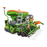
Amazone Centaya 3000 Super 2000 Operating Manual (230 pages)
Pneumatic pack top seed drill
Brand:
Amazone
| Category:
Farm Equipment
| Size: 41 MB
Table of Contents
Table of Contents
5
1 User Information
10
Purpose of the Document
10
Locations in the Operating Manual
10
Diagrams
10
2 General Safety Instructions
12
Obligations and Liability
12
Representation of Safety Symbols
14
Organisational Measures
15
Safety and Protective Equipment
15
Informal Safety Measures
15
User Training
16
Safety Measures in Normal Operation
17
Danger from Residual Energy
17
Maintenance and Repair Work, Fault Elimination
17
Design Changes
18
Spare and Wear Parts and Aids
19
Cleaning and Disposal
19
User Workstation
19
Warning Symbols and Other Labels on the Implement
20
Position of Warning Symbols
24
Dangers in Case of Non-Compliance with the Safety Instructions
26
Safety-Conscious Working
26
Safety Information for Users
27
General Safety Instructions and Accident Prevention Instructions
28
Hydraulic System
32
Electrical System
32
Mounted Implements
34
Operation of the Seed Drill
35
Cleaning, Maintenance and Repair
35
3 Loading and Unloading the Implement Upon Delivery
36
4 Product Description
39
Components of the AMAZONE Seeding Combination
39
Equipment Variations of the Centaya Pneumatic Pack Top Seed Drill
40
Components of the Centaya Pneumatic Pack Top Seed Drill
42
Safety and Protective Equipment
44
Overview - Supply Cable / Hydraulic Hose Lines
45
Supply Cable
45
Identification of the Hydraulic Hose Lines
45
Type of Actuation of the Tractor Control Units
45
Connection and Function of the Tractor Control Units
46
Comfort Hydraulic System - Implements with ISOBUS System
47
Traffic Safety Equipment
48
Intended Use
49
Approved AMAZONE Implement Combinations
50
Danger Areas and Danger Points
51
Rating Plate and CE Mark
52
Technical Data
53
Noise Production Data
53
Technical Data for Calculating the Tractor Weight and the Tractor Axle Loads
54
Required Tractor Equipment
55
5 Layout and Function
56
AMAZONE Amadrill 2 Control Terminal
59
AMAZONE Calibration Button
59
Control Terminal for Implements with ISOBUS System
59
AMAZONE Amatron 4 Control Terminal
60
AMAZONE Twinterminal
60
Implement Documentation
61
Central Key
61
Hand Wash Tank
61
Radar Device
62
Seed Hopper and Loading Board
63
Fill Level Monitoring
64
Metering
65
Metering Roller Diagram Table - Figures
67
Calibrating the Seed Rate
72
Blower Fan
75
Distributor Head
77
Seed Tube Monitoring
78
Spreading Seed with Wide Row Spacing
79
Rotec-Pro Control Coulter
80
Twintec Double Disc Coulter
82
Seed Placement Depth (Twintec)
84
Coulter Pressure, Seed Rate Increase and Coulter Lift (All Coulter Types - Hydraulically Actuated)
85
5.12.1.1 Coulter Pressure
85
5.12.1.2 Activating the Seed Rate Increase
86
5.12.1.3 Coulter Lift
87
Exact Following Harrow
88
Exact Following Harrow Tine Position
89
Exact Following Harrow Pressure
90
Seeding Without Exact Following Harrow (Exact Following Harrow Lift)
91
Seed Pre-Metering
92
Start-Up Ramp
92
Tramlines
93
Tramline Rhythm, Tabular Determination
96
Tramline Rhythm, Graphic Determination
96
One-Sided Switching
98
5.16.3.1 One-Sided Switching by Installing an Insert
98
5.16.3.2 One-Sided Switching by Actuating a Lever
99
5.16.3.3 One-Sided Switching by Pressing a Button on the Control Terminal
100
Tramline Marker
101
Tramline Marker with Bracket on the Implement Frame
101
Tramline Marker with Bracket on the Exact Following Harrow
102
Track Marker
103
Camera System
104
Headlight
105
Greendrill 200E
106
6 Start-Up
107
Checking the Suitability of the Tractor
108
Calculating the Actual Values for the Total Tractor Weight, Tractor Axle Loads and Tyre Load-Bearing Capacity, as Well as the Required Minimum Ballast Weight
109
Data Required for the Calculation (Attached Implement)
110
To Ensure Steering Capability
111
Min of the Tractor
111
Calculation of the Actual Front Axle Load of the Tractor T
111
Calculation of the Actual Total Weight of the Combined Tractor and Implement
111
Tat
111
Calculation of the Actual Rear Axle Load of the Tractor T
111
Load-Bearing Capacity of the Tractor Tyres
111
H Tat
111
Table
112
Secure the Tractor / Implement against Unintentional Starting and Rolling Away
113
Hydraulic Connection for the Blower Fan Drive
114
7 Coupling and Uncoupling the Implement
115
Hydraulic Hose Lines
117
Coupling the Hydraulic Hose Lines
117
Disconnecting the Hydraulic Hose Lines
118
Coupling and Uncoupling Implements
119
Coupling - Tractor and Soil Tillage Implement
121
Installation of the Analogue Working Position Sensor and the Working Position Sensor for the Seed Tube Monitoring
122
Coupling - Pack Top Seed Drill and Soil Tillage Implement
126
Uncoupling - Combination and Tractor
130
Uncoupling - Soil Tillage Implement and Pack Top Seed Drill
131
Checking the Tramline Track Width
136
Checking the Tramline Wheelmark Width
136
8 Settings
137
Folding the Steps up and down
138
Fill the Seed Hopper
140
Calibrating the Seed Rate
143
Setting the Blower Fan Speed
149
Setting the Blower Fan Speed Via the Flow Control Valve of the Tractor
150
Setting the Blower Fan Speed on Tractors Without Flow Control Valve
150
Switching on the Blower Fan Speed Monitoring
150
Pressure Relief Valve with Round Outer Contour
151
Basic Setting of the Pressure Relief Valve
151
Blower Fan Speed Setting
151
Pressure Relief Valve with Hexagonal Outer Contour
152
Basic Setting of the Pressure Relief Valve
152
Blower Fan Speed Setting
152
Rotec-Pro Control Coulter
153
Adjusting and Checking the Seed Placement Depth
153
Adjusting the Depth Control Discs / Wheels
154
Twintec Double Disc Coulter
156
Adjusting and Checking the Seed Placement Depth
156
Coulter Pressure, Seed Rate Increase and Coulter Lift (All Coulter Types - Hydraulically Actuated)
160
Increasing / Reducing the Coulter Pressure
161
Adjusting the Seed Rate Increase
161
Soil Tillage Without Seeding (Coulter Lift)
162
Adjusting the Exact Following Harrow
163
Adjusting the Exact Following Harrow Tines
163
Setting the Exact Following Harrow Pressure
164
Moving the Exact Following Harrow to the Working/Transport Position
165
Move the Exact Following Harrow into Working Position
165
Moving the Exact Following Harrow into Transport Position
165
Seeding Without Exact Following Harrow (Exact Following Harrow Lift)
165
Moving the Track Marker to the Working / Transport Position
166
Move Track Marker to Working Position
166
Moving the Track Marker to Transport Position
168
One-Sided Switching
169
One-Sided Switching - Installing an Insert
169
One-Sided Switching - Lever Actuation
170
One-Sided Switching - Setting on the Control Terminal
170
Moving the Tramline Marker into Working/Transport Position
171
Moving the Tramline Marker with Frame Bracket to Working Position
171
Moving the Tramline Markers with Frame Bracket to the Transport Position
172
Move the Tramline Marker to Working Position with Exact Following Harrow Bracket
173
Move the Tramline Marker to Working Position with Exact Following Harrow Bracket
174
Moving the Exact Following Harrow Road Safety Bar into Road Transport/Parking Position
175
Moving the Road Safety Bar into Road Transport Position
175
Moving the Road Safety Bar into Parking Position
175
9 Transportation
176
Moving the Seeding Combination into Transport Position
176
Legal Regulations and Safety
177
10 Use of the Implement
181
Initial Operation
182
Headlight
182
Moving the Implement from Transport into Working Position
183
Work Commencement
183
During Operation
185
Overview of Checks During Operation
185
Turning at End of the Field
186
Track Marker
187
End of Work on the Field
188
Emptying the Hopper and Metering Unit and Replacing the Metering Roller
189
Quick Emptying of the Hopper
190
Emptying the Hopper And/Or Metering Unit and Replacing the Metering Roller
191
11 Faults
194
Residual Seed Quantity Display
195
Deviations between the Set and Actual Seed Rate
195
12 Cleaning, Maintenance and Repairs
196
Safety
196
Safety When Working on Hydraulic Hose Lines
198
12.1.1.1 Safety through Labelling the Hydraulic Hose Lines
199
Safety When Cleaning the Implement
200
Safety When Working on the Distributor Head
202
Cleaning the Implement
202
Cleaning the Fan Suction Guard Screen
202
Cleaning the Blower Fan
202
Clean the Distributor Head
203
Lubrication Schedule
204
Lubrication Points
204
Maintenance Schedule
205
Adjustment and Maintenance Work
207
Mount the Plugs in the Distributor Head for Spreading Seed with Wide Row Spacing
207
Parking the Implement for a Longer Period of Time
208
Visual Inspection of the Upper and Lower Link Pins
208
Work to be Performed in a Specialist Workshop
209
Checking the Hydraulic Hose Lines
209
Adjusting the Tramlines on the Distributor Head
210
12.7.2.1 Adjusting the Tramline Track Width on the Distributor Head
211
12.7.2.2 Adjusting the Tramline Wheelmark Width on the Distributor Head
211
12.7.2.3 Removing and Installing the Segment in the Distributor Head
212
12.7.2.4 Electrical Connection of the Tramline Segments
213
12.7.2.5 Deactivating Tramline Segments
214
Replacing the Grid on the Rotec Pro Control Coulter
215
Checking and Readjusting the Twintec Disc Bearings
216
12.7.4.1 Checking the Twintec Disc Bearings
216
12.7.4.2 Readjusting the Twintec Disc Bearings
216
Dismounting the Twintec Seed Line
218
Checking / Replacing the Twintec Inner Scraper
218
Checking / Replacing the Twintec Baffle Lip
219
Advertisement
Amazone Centaya 3000 Super 2000 Original Operating Manual (174 pages)
Pneumatic pack top seed drill
Brand:
Amazone
| Category:
Drill
| Size: 5 MB
Table of Contents
Table of Contents
3
About this Operating Manual
7
Diagrams
7
Warnings and Signal Words
7
Further Instructions
7
Instructions
8
Lists
9
Item Numbers in Figures
9
Other Applicable Documents
10
Your Opinion Is Important
10
Safety and Responsibility
11
Basic Safety Instructions
11
Meaning of the Operating Manual
11
Safe Operating Organisation
11
Knowing and Preventing Dangers
16
Safe Operation and Handling of the Machine
17
Safe Maintenance and Modification
19
Safety Routines
23
Intended Use
25
Product Description
26
Implement Overview
26
Function of the Implement
28
Special Equipment
28
Protective Equipment
29
Metering Unit Guard Screen
29
Fan Guard Screen
30
Road Safety Bar
30
Warning Symbols
31
Positions of the Warning Symbols
31
Layout of the Warning Symbols
32
Description of the Warning Symbols
33
Rating Plate on the Implement
37
Smartcenter
37
Threaded Cartridge
38
Hand Wash Tank
38
Universal Operating Tool
39
Hopper
39
Conveyor Fan
40
Metering System
40
Metering Unit
40
Metering Roller
41
Conveyor Sections
41
Cyclone Separator
42
Mounting Frame
43
Lighting
43
Rear Lighting and Identification for Road Travel
43
Work Lights
44
Hopper Interior Lighting
45
Segment Distributor Head
45
One-Sided Switching
46
Twintec Coulter
47
Rotec Coulter
47
Exact Following Harrow
48
Coulter Harrow
49
Roller Harrow
49
Tramline Marker
50
Track Marker
50
Camera System
51
Greendrill
51
Micropellet Spreader
52
Technical Data
53
Hopper Volume
53
Dimensions
53
Quicklink Quick-Coupling System
54
Optimal Working Speed
54
Soil Tillage Tools
54
Permitted Mounting Categories
54
Noise Development Data
55
Drivable Slope Inclination
55
Performance Characteristics of
55
The Tractor
55
Preparing the Implement
57
Calculating the Required Tractor Characteristics
57
Coupling the Implement
60
Coupling the Hydraulic Hose Lines
60
Coupling the ISOBUS Line
62
Coupling the Power Supply
62
Connecting the Camera System
63
Coupling the 3-Point Mounting Frame
63
Coupling the Centaya Pack Top Seed Drill
63
Coupling the Ftender Conveyor Line
66
Preparing the Implement for
66
Operation
66
Adjusting the Working Position Sensor
66
Opening and Closing the Roller Tarpaulin
67
Setting the Fill Level Sensor
67
Adjusting the Volume Division of the 2-Chamber Hopper
69
Filling the Hopper
72
Adjusting the Placement Depth on the Twintec Coulter
73
Adjusting the Placement Depth on the Rotec Coulter
73
Adjusting the Coulter Pressure
75
Lifting the Coulters
76
Adjusting the Coulter Harrow
76
Adjusting the Exact Following Harrow
80
Adjusting the Roller Harrow
85
Adjusting the Tramline Marker
87
Operating the One-Sided Switching
94
Adjusting the Fan Speed Hydraulically
95
Adjusting the Fan Speed Manually
96
Adjusting the Row Spacing
97
Setting up the Speed Sensor
98
Operating the Loading Board with Steps
99
Preparing the Metering Unit for Operation
99
Preparing the Machine for Road Travel
110
Folding the Tramline Marker Onto the Implement Frame
110
Folding the Tramline Marker on the Exact Following Harrow
110
Moving the Exact Following Harrow into Transport Position
110
Attaching the Road Safety Bar on the Exact Following Harrow
111
Calculating the Permissible Payload
112
Using the Implement
113
Checking the Placement Depth
114
Turning on the Headlands
114
Eliminating Faults
115
Parking the Implement
122
Emptying the Hopper
122
Emptying the Hopper Via the Quick Emptying
122
Emptying the Hopper Via the Metering Unit
123
Emptying the Metering Unit
127
Disconnecting the Hydraulic Hose Lines
130
Uncoupling the ISOBUS Line
131
Uncoupling the Power Supply
132
Uncoupling the Ftender Conveyor Line
132
Uncoupling the Seeding Combination
133
Parking the Centaya Pack Top Seed Drill
134
Repairing the Implement
138
Maintaining the Implement
138
Checking the Twintec Concave Disc
139
Checking the Twintec Concave Disc Spacing
140
Checking the Twintec Depth Control Wheel
141
Checking the Twintec Depth Control Wheel Scraper
142
Checking the Rotec Depth Control Discs and Rotec Depth Control Wheels
143
Checking the Cutting Discs
144
Cleaning the 1-Chamber Hopper
145
Cleaning the 2-Chamber Hopper
146
Cleaning the Hand Wash Tank
148
Cleaning the Conveyor Section
148
Cleaning the Segment Distributor Head
150
Checking the Tightening Torque for the Radar Sensor Bolts
151
Cleaning the Metering Unit
151
Cleaning the Cyclone Separator
155
Checking the Top Link Pin and Lower Link Pin
155
Checking the Hydraulic Hose Lines
156
Checking the Rotec Furrow Former
157
Lubricating the Implement
158
Overview of Lubrication Points
159
Cleaning the Implement
160
Loading the Implement
161
Installing a Lashing Point in the Hopper
161
Lifting the Implement
163
Lashing the Implement
163
Appendix
165
Bolt Tightening Torques
165
Other Applicable Documents
166
Directories
167
Glossary
167
Maintenance Schedule 132 13.2 Index
168
Advertisement
Related Products
Amazone Centaya 4000 Super 2000
Amazone Centaya 3500 Super 2000
Amazone Centaya
Amazone Centaur 6001
Amazone Centaur 3002
Amazone Centaur 4002
Amazone Cenius 3003
Amazone Cenius 4003
Amazone Cenius Super
Amazone Cenius Special
Amazone Categories
Farm Equipment
Tiller
Spreader
Desktop
Paint Sprayer
More Amazone Manuals
Login
Sign In
OR
Sign in with Facebook
Sign in with Google
Upload manual
Upload from disk
Upload from URL