
Related Manuals for J&M TF2


Summary of Contents for J&M TF2
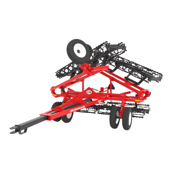
- Page 1 OPERATORS MANUAL TF212 TF215 J. & M. Mfg. Co., Inc. 284 Railroad Street - P .O. Box 547 Fort Recovery, OH 45846 Ph: (419) 375-2376 Fax: (419) 375-2708 www.jm-inc.com...
-
Page 2: Table Of Contents
Outside Wing Wheel Assemblies Torsion Arm Rolling Baskets Coil Tine & Diagonal Bar TF2 Hydraulic Layout TF212-TF215 2 Hoses w/ Lift Assist Hydraulic Layout 26-27 TF212-TF215 4 Hoses w/ Lift Assist Hydraulic Layout 28-29 TF212-TF215 4 Hoses WITHOUT Lift Assist Hydraulic Layout... -
Page 3: To The Dealer
To The Dealer General Information Read manual instructions and safety rules. Make sure all items on the Dealer’s Pre-Delivery and Delivery Check Lists are completed before releasing equipment to the owner. The dealer must complete the Warranty Registration found on the Dealer Portal website located at dealer.jm-inc.com and return it to J. -
Page 4: General Information
General Information To The Dealer TO THE OWNER: The purpose of this manual is to assist you in operating and maintaining your soil conditioner in a safe manner. Read it carefully. It furnishes information and instructions that will help you achieve years of dependable performance and help maintain safe operating conditions. -
Page 5: Bolt Torque Chart
General Information Bolt Torque Chart BOLT TORQUE CHART Always tighten hardware to these values unless a different torque or tightening procedure is listed for a specific application. Fasteners must always be replaced with the same grade as specified in the manual parts list. Always use the proper tool for tightening hardware. -
Page 6: Specifications
Specifications To The Dealer Specifications Basket Sizes & Layout Working Transport Base Wings Each Approx. Side Wing Base Unit Side Wing Width Width Width Width 12’ 12’ 12’ 2,195 lbs. 6’ 6’ 13’ 13’ 12’ 2,310 lbs. 4’ 5’ 4’ 14’... -
Page 7: Safety Rules
Safety Rules ATTENTION! BECOME ALERT! YOUR SAFETY IS INVOLVED! Safety is a primary concern in the design and manufacture of our products. Unfortunately, our efforts to provide safe equipment can be erased by an operator’s single careless act. In addition, hazard control and accident prevention are dependent upon the awareness, concern, judgment, and proper training of personnel involved in the operation, trans- port, maintenance and storage of equipment. -
Page 8: Safety Signs
JM0009945 9 Reflective Orange Decal JM0009944 10 Medium Size J&M Oval JM0010179 11 Small “J&M Manufacturing” Decal JM0010180 12 “TF2” Decal Driver Side JM0027693 12 “TF2” Decal Passenger Side JM0027688 12 “TF212” Decal Drivers Side JM0027692 12 “TF212” Decal Passenger Side JM0027689 12 “TF215”... - Page 9 Set-Up Instruction The J&M Torsion-Flex Soil Conditioner is shipped with components partially assembled. Hardware required to connect the Base Wheel Assembly, Main Base Frame Assembly, Wing Frames and Tongue Assembly should already be secured to the components at the point of attachment.
-
Page 10: Set-Up Instructions
Set-Up Instructions To The Dealer • Wheel Arm Weldment Turnbuckle Attach the wheel are weldment to the main frame. Use a 1-1/4” x 9 “ hex bolt and 1-1/4” hex nut. Tighten hardware. • Wheel & Tire Assembly Attach the wheel and tire assembly using (6) 1/2” wheel nuts. Lift Cylinder Align the wheel and hub and tighten the wheel nuts in a star pattern to 80 Ft. - Page 11 General Information Set-Up Instructions • Base Unit Baskets Torsion Arms Attach the 3’ Heavy Torsion arms to the rolling basket. Secure with 1” x 6-1/2” hex 3” x 3” Rocker Pad bolt and 1” nylon locking hex nut. Fasten hardware once secured. (Rocker Pads may need installed.
- Page 12 Set-Up Instructions To The Dealer Torsion Arms • Wing Baskets 2-1/2” x 2-1/2” Attach the 2’ Light Torsion arms to the rolling basket. Secure with 1” x 6-1/2” Rocker Pad hex bolt and 1” nylon locking hex nut. Fasten hardware once secured. (Rocker Pads may need installed.
- Page 13 General Information Set-Up Instructions • Coil Tine Spring Assembly 1/2” x 4-1/8” x 5” U-Bolt For part identification, refer to page 24. For Coil Tine Spring Assembly layout see page 14. Attach the Coil Tine Spring Assembly to the main frame or wing weldment. Secure the Coil Tine Spring Assembly with (2) 1/2”...
-
Page 14: Coil Tine Pipe Bar & Round Bar Bracket Layout
Coil Tine Pipe Bar & Round Bar Bracket Layout To The Dealer Below is a recommended layout of the harrow pipe bar and round bar bracket lengths along the width of the conditioner. Be sure the Harrow is properly and evenly spaced along the Base Unit Main Frame and Wing Frames, making adjustments as necessary. -
Page 15: Operations
Operations PREPARING THE TORSION-FLEX SOIL CONDITIONER Before putting the soil conditioner into operation, check the machine for damaged or worn parts and replace as necessary. Hardware Make sure all hardware is properly fastened according to the Bolt Torque chart found in this manual. Recheck all hardware for tightness after the unit has been operated for several hours. -
Page 16: Transporting, Un-Hitching, Field Adjustments
Transporting Before the soil conditioner is transported, be sure to secure the Jack Assembly in the transport position located on the top of the Storage Extension Arm. The Torsion-Flex Soil Conditioner will increase the overall length of the primary tillage tool. Use extreme caution when turning to avoid obstacles. Reduce ground speed as necessary to maintain control of equipment. -
Page 17: Storage, Service, Troubleshooting
Storage To add longer service and life to your Torsion-Flex Soil Conditioner, perform the following before placing the implement in storage: 1. Remove dirt and trash that may cause rusting. 2. Repaint any areas where the paint has been chipped, scratched or worn away. 3. -
Page 18: Parts List
JM0001663 Telescoping Hitch Weldment JM0026437 Cotter Pin (Sold with item #5) JM0028344 1" x 8" Tounge Pin JM0027117 A-Frame Tongue Weldment (TF2) JM0027700 A-Frame Tongue Weldment (TF212) JM0026439 A-Frame Tongue Weldment (TF215) JM0026444 1-1/4"-7 x 6" Gr5 Z Hex Bolt JM0016690 1-1/4"-7 Gr5 Z Nylon Locking Hex Nut... -
Page 19: Main Frame Assembly
17 1-3/4" x 4" Wing Pin JM0026689 18 7/16" x 2-3/4" Z Roll Pin JM0009895 19 Base Unit Main Frame (TF2 – 12’ or 13’ working width) JM0031862 19 Base Unit Main Frame (TF2 – 14’ or 15’ working width) JM0031863 19 Base Unit Main Frame (TF2 –... -
Page 20: Outside Wing
Outside Wing Assembly To The Dealer Description Part. No. 4" Wing Pin JM0026689 7/16" x 2-3/4" Z Roll Pin JM0009895 Pivot Linkage Arm Weldment (TF212) JM0026682 Pivot Linkage Arm Weldment (TF215) JM0026683 1-3/4"-5 Gr5 Hex Nut JM0019334 1-3/4" x 6-3/8" Wing Bolt JM0026691 1-3/4"... -
Page 21: Wheel Assemblies
1-1/4"-7 Gr5 Z Nylon Locking Hex Nut JM0026789 Wheel Arm Weldment - Right (TF212-TF215) JM0026714 Wheel Arm Weldment - Left (TF212-TF215) JM0026713 Wheel Arm Weldment - Main Frame (TF2) JM0031866 Wheel Arm Weldment - Main Frame (TF212-TF215) JM0026696 Cotter Pin JM0016381... -
Page 22: Torsion Arm
Torsion Arm # Description Part. No. 1 Square U-bolt 4-1/8" Inside Width x 6" Length, 5/8"-11TH JM0014190 2 Short 3' Heavy Torsion Arm Weldment JM0008446 2 Short 2' Heavy Torsion Arm Weldment JM0008447 2 Short 2’ Light Torsion Arm Weldment JM0008448 2 Long 3’... -
Page 23: Rolling Baskets
Rolling Basket Optional Upgraded Basket Hub Description Part. No. Description Part. No. 1-1/4"-12 x 3-1/4" Gr5 Z Hex Bolt JM0001529 5' Crazy Leg Weldment JM0001768 3/4” x 3-1/2 ” Gr8 Z Hex Bolt (Upgraded Basket Hub) JM0042405 4' Crazy Leg Weldment JM0001767 1/2"-13 x 1-1/4"... -
Page 24: Coil Tine & Diagonal Bar
Coil Tine Pipe Bar and Round Bar Bracket Description Part. No. 1/2"-13 x 5" Gr5 Z Hex Bolt JM0001594 Harrow Squeeze Block JM0027006 1/2-13 Gr5 Z x 4-1/4" J-Bolt JM0020373 3'8" Wide Coil Tine Pipe JM0026999 4'8" Wide Coil Tine Pipe JM0026996 5'8"... -
Page 25: Tf2 Hydraulic Layout
TF2 (12’ to 18’ Working Width) Lift Cylinders Lift Cylinders Hoses To Tractor # Description Part. No. 1 3/8” x 264” Hydraulic Hose JM0030831 2 3/8” x 77” Hydraulic Hose JM0027152 3 3/8” x 44” Hydraulic Hose JM0027155 3/8” x 32” Hydraulic Hose JM0027143 5 3/8”... -
Page 26: Tf212-Tf215 2 Hoses W/ Lift Assist Hydraulic Layout
TF212-TF215 with Lift Assist (2 Hoses) - Page 27 TF212-TF215 with Lift Assist (2 Hoses) Description Part. No. 1/2" x 336" Hydraulic Hose (TF212) (HH-12336) JM0027137 1/2" x 384" Hydraulic Hose (TF215) (HH-12384) JM0027263 3/8" x 200" Hydraulic Hose (TF212)(32' , 33') JM0027129 3/8" x 219" Hydraulic Hose (TF212)(34' , 35') JM0027125 3/8"...
-
Page 28: Tf212-Tf215 4 Hoses W/ Lift Assist Hydraulic Layout
TF212 EQUIPPED with 2 sets of hoses & optional Wing Wheels... - Page 29 TF212 EQUIPPED with 2 sets of hoses & optional Wing Wheels Description Part. No. 1/2" x 336" Hydraulic Hose JM0027264 3/8" x 210" Hydraulic Hose JM0027124 3/8" x 222" Hydraulic Hose JM0027125 3/8" x 234" Hydraulic Hose JM0027126 3/8" x 174" Hydraulic Hose JM0027127 3/8"...
-
Page 30: Tf212-Tf215 4 Hoses Without Lift Assist Hydraulic Layout
TF212 & TF215 EQUIPPED with 2 set of hoses, w/out optional Wing Wheels... -
Page 31: Tf212-Tf215 2 Hoses Without Lift Assist Hydraulic Layout
TF212 & TF215 EQUIPPED with 1 set of hoses, w/out optional Wing Wheels... -
Page 32: Light Harness
Light Harness To The Dealer Description Part. No. Base Harness JM0027080 A-Frame Harness JM0027077 Light Enhancer JM0010566...
Need help?
Do you have a question about the TF2 and is the answer not in the manual?
Questions and answers