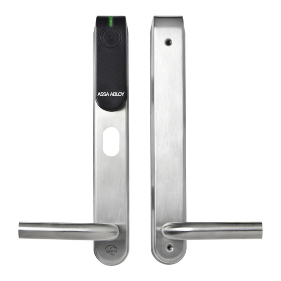
Assa Abloy Aperio Installation & Integration
Hide thumbs
Also See for Aperio:
- Quick installation manual (28 pages) ,
- Quick installation manual (28 pages) ,
- Install manual (9 pages)
Table of Contents
Advertisement
Advertisement
Table of Contents

Summary of Contents for Assa Abloy Aperio
- Page 1 Certification Exhibit FCC ID: U4A-AHGUHF00 IC: 6982A-AHGUHF00 FCC Rule Part: 15.247 IC Radio Standards Specification: RSS-210 ACS Report Number: 10-0344.W06.11.A Manufacturer: Assa Abloy Model: AH13 Manual 5015 B.U. Bowman Drive Buford, GA 30518 USA Voice: 770-831-8048 Fax: 770-831-8598...
- Page 2 Aperio Installation & Integration Instructions WFMN5A 11MAR 2011 EMEA Form: AAWL-260 01/31/11 Copyright © 2011, ASSA ABLOY All rights reserved. Reproduction in whole or in part without the express written permission of ASSA ABLOY is prohibited.
-
Page 3: Table Of Contents
Warnings: Changes or modifications to this device not expressly approved by ASSA ABLOY could void the user’s authority to operate the equipment. “This equipment complies with FCC radiation exposure limits set forth for an uncontrolled environment. This equipment should be installed and operated with minimum distance 20cm between the radiator and your body. -
Page 4: Chapter 1: Technical Specifications
Aperio technology version 2.3.0 and later. System When a user presents a supported credential to the lock the Aperio system is designed to send the credential wirelessly to the Communication Hub. The Communication Hub (wired through RS-485 or Description Wiegand) then communicates with an EAC (Electronic Access Control) system. -
Page 5: Chapter 3: Install The Communication Hub
Keep at least 8-10 feet (2.5m) distance between the Communication Hub and lock. Copyright © 2011, ASSA ABLOY All rights reserved. Reproduction in whole or in part without the express written permission of ASSA ABLOY is prohibited. WFMN5A • PAGE 4... -
Page 6: Ah20 Integration(Wiegand)
ON: Selects use of internal antenna. OFF: Selects use of external antenna. Copyright © 2011, ASSA ABLOY All rights reserved. Reproduction in whole WFMN5A • PAGE 5 or in part without the express written permission of ASSA ABLOY is prohibited. -
Page 7: Ah20 Dip Switch Configuration Table
1 on previous page for alternate instructions. Ground Connect to EAC System ground. 8-24 VDC 8-24 VDC Copyright © 2011, ASSA ABLOY All rights reserved. Reproduction in whole or in part without the express written permission of ASSA ABLOY is prohibited. WFMN5A • PAGE 6... -
Page 8: Connections For Ah20 (J103)
If communication is established, the LED will have a steady green light. Copyright © 2011, ASSA ABLOY All rights reserved. Reproduction in whole WFMN5A • PAGE 7 or in part without the express written permission of ASSA ABLOY is prohibited. -
Page 9: Ah13/Ah30 Dip Switch Configuration
ON =>Selects use of internal antenna. OFF => Selects use of external antenna. Copyright © 2011, ASSA ABLOY All rights reserved. Reproduction in whole or in part without the express written permission of ASSA ABLOY is prohibited. WFMN5A • PAGE 8... -
Page 10: Connections For Ah13/Ah30
Address ƒ By use of the DIP switch (See Dip1-Dip4 on Page 9). RS-485 address from DIP switch through the Aperio Programming Application tool: the Selecting the APA tool maybe used to remotely set or override the physical dip switch address setting. When the Communication Hub is set with the APA tool the physical dip switch settings are ignored. -
Page 11: Rs485 Bus Connection
DIP 8 ON Figure 4. Examples, Communication Hub Connections Figure 5. Address Examples Copyright © 2011, ASSA ABLOY All rights reserved. Reproduction in whole or in part without the express written permission of ASSA ABLOY is prohibited. WFMN5A • PAGE 10... -
Page 12: Physical Hub Installation
Octagon Box Assembly Switch Box Assembly Square Box Assembly Figure 6. Communication Hub Assembly Copyright © 2011, ASSA ABLOY All rights reserved. Reproduction in whole WFMN5A • PAGE 11 or in part without the express written permission of ASSA ABLOY is prohibited. -
Page 13: Hub Led Indication
Figure 7. Communication Hub Normal LED Indications Yellow Pairing Active Figure 8. Communication Hub Normal LED Indications Copyright © 2011, ASSA ABLOY All rights reserved. Reproduction in whole or in part without the express written permission of ASSA ABLOY is prohibited. WFMN5A • PAGE 12... - Page 14 Notes...
- Page 15 ASSA ABLOY is the global leader in door opening solutions, dedicated to satisfying end user needs for security, safety and WFMN5A • 01/11 convenience...


Need help?
Do you have a question about the Aperio and is the answer not in the manual?
Questions and answers