
Related Manuals for Assa Abloy aperio AH20 GEN5


Summary of Contents for Assa Abloy aperio AH20 GEN5
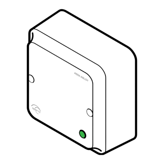
- Page 1 Aperio ® AH20/AH30 (GEN5) Hub Installation Guide Experience a safer and more open world...
-
Page 2: Table Of Contents
AH20/AH30 - Table of Contents AH20/AH30 - FCC and ISED Canada Statements ..........3 AH20/AH30 - Placement of Communication Hub ......... 5 AH20/30 - Mounting, Americas Adapter Plate (US version)....... 6 AH20/30 - Mounting, Bottom Cover (EU version) ......... 7 AH20 (J101) - Connections ................... -
Page 3: Ah20/Ah30 - Fcc And Ised Canada Statements
AH20/AH30 - FCC and ISED Canada Statements FCC Statements Changes or modifications to the equipment not expressly approved by the party responsible for compliance could void the users authority to operate the equipment. This device complies with Part 15 of the FCC Rules. Operation is subject to the following two conditions: (1) This device may not cause harmful interference, and (2) This device must accept any interference received, including interference that may cause undesired operation. - Page 4 This device contains licence-exempt transmitter(s)/receiver(s) that comply with Innovation, Science and Economic Development Canada’s licence- exempt RSS(s). Operation is subject to the following two conditions: (1) This device may not cause interference. (2) This device must accept any interference, including interference that may cause undesired operation of the device.
-
Page 5: Ah20/Ah30 - Placement Of Communication Hub
AH20/AH30 - Placement of Communication Hub For hubs using the internal For hubs using the external antenna, it is recommended antenna, it is recommended that the device to hub distance that the device to hub distance be limited to 25 m (80 ft). The be limited to 12.5 m (40 ft). -
Page 6: Ah20/30 - Mounting, Americas Adapter Plate (Us Version)
AH20/30 - Mounting, Americas Adapter Plate (US version) AH40 - Mounting, Americas Adapter Plate Americas Adapter Plate Screw (4 x 35 mm) Tamper Screw switch (3 x 10 mm) Option External Antenna... -
Page 7: Ah20/30 - Mounting, Bottom Cover (Eu Version)
AH40 - Mounting, Bottom Cover AH20/30 - Mounting, Bottom Cover (EU version) Bottom Cover Tamper Screw Screw switch pin (4 x 35 mm) (3 x 10 mm) Option External Antenna... -
Page 8: Ah20 (J101) - Connections
AH20 (J101) - Connections TERM NCL1 COM1 NOP1 NCL2 COM2 NOP2 NCL3 COM3 GREEN NOP3 NCL4 COM4 8-24VDC NOP4 AH20 Advanced Wiegand Connectors (J101) TERM GREEN 8-24VDC AH20 Standard Wiegand Connectors (J101) Note: The installation must comply with national wiring regulations. - Page 9 Communication Hub hardware version AH20 has four Wiegand signals plus power supply. The purpose and connection of these signals are described in the table below. esCription onneCtor Wiegand Data 1 signal. Output from Communication Hub. Used to transmit credentials. Wiegand Data 0 signal. Output from Communication Hub. Used to transmit credentials.
-
Page 10: Ah20 Advanced Wiegand (J100) - Connections
AH20 Advanced Wiegand (J100) - Connections TERM NCL1 COM1 NOP1 NCL2 COM2 NOP2 NCL3 COM3 GREEN NOP3 NCL4 COM4 8-24VDC NOP4 AH20 Advanced Wiegand Connectors (J100) On the AH20 advanced elays esCription Wiegand communication hub, four form C relays are Relay 1 DPS (Door Position) available. -
Page 11: Ah20 - Dip Switch Configuration Table (S700)
AH20 - DIP Switch Configuration Table (S700) witCH abel esCription umber Controls use of Red LED signal for access decision. ON => Red LED is used. OFF => Red LED is ignored. Set to OFF by default. Reserved for future use. Controls addition of parity bits if required. -
Page 12: Ah30 (J101) - Connections
AH30 (J101) - Connections TERM TERM GREEN 8-24VDC AH30 (J101) Connectors esCription onneCtor RS485 Data A. RS485 Data B. GND = Signal ground. Should be connected to EAC system GND and power supply GND. Power supply input, 8-24 VDC, 2 W (AH20 Advanced) 8-24 VDC alternatively 0.8 W (AH20 Standard and AH30). -
Page 13: Ah30 - Dip Switch Configuration Table (S700)
AH30 - DIP Switch Configuration Table (S700) witCH abel esCription umber Controls RS485 addressing BIT 0-BIT 4. ON => Address bit set. A0-A4 OFF => Address bit NOT set. See AH30 - RS485 Addressing Reference on page Control use of termination resistor between RS485 A and RS485 B. -
Page 14: Ah30 - Rs485 Bus Connection
AH30 - RS485 Bus Connection Here are examples of connection of multiple Communication Hubs to a single RS485 bus of an EAC system. Termination should be enabled to the last Hub on the bus. The Daisy chain is the recommended connection scheme. Hub 1 EAC system Termination... -
Page 15: Ah30 - Rs485 Addressing
AH30 - RS485 Addressing DDress Pairing Active* Address examples *) Note: If any of the A0-A4 DIP switches are moved from OFF to ON within 10 seconds from boot up and the Hub LED is lit, all paired devices will be unpaired. - Page 16 DDress Address examples *) A4 is only supported on AH30 in 1 - 1 mode.
-
Page 17: Ah20/Ah30 - Communication Hub Led Indication
AH20/AH30 - Communication Hub LED Indication The Communication Hub has a single LED that supports an optical scheme with red, green and yellow. The indication scheme is described by the two figures below: Online Green Aperio Lock Green + One ®... -
Page 18: Ah20/Ah30 - Technical Data
Internal Antenna Two cross polarized dipoles. One reverse polarity SMA external antenna connector. AH20/30 is certified to be used with ASSA ABLOY External Antenna external antenna AH-ANTENNA-1. If other external antenna is used it must be of same type (dipole) and not have larger antenna gain than 3.6 dBi. - Page 19 NOTE...
- Page 20 The ASSA ABLOY Group is the global leader in access solutions. Every day we help people feel safe, secure and experience a more open world. Contact www.assaabloy.com/aperio...
Need help?
Do you have a question about the aperio AH20 GEN5 and is the answer not in the manual?
Questions and answers