Table of Contents
Advertisement
Quick Links
Advertisement
Table of Contents

Related Manuals for CAB 5314


Summary of Contents for CAB 5314
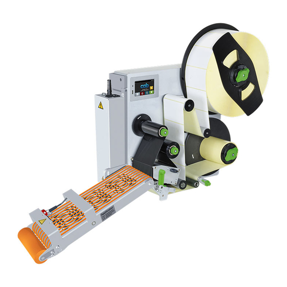
- Page 1 Operator's Manual Vacuum-Belt 5314 / 5316 Applicator Made in Germany...
- Page 2 No. 9009884 Copyright This documentation as well as translation hereof are property of cab Produkttechnik GmbH & Co. KG. The replication, conversion, duplication or divulgement of the whole manual or parts of it for other intentions than its original intended purpose demand the previous written authorization by cab.
-
Page 3: Table Of Contents
Table of Contents Introduction ............................4 Instructions ............................... 4 Intended Use ............................4 Safety Instructions ............................ 4 Safety Markings ............................5 Environment ............................. 5 Product Description ..........................6 Important Features ........................... 6 Technical Data ............................6 Overview ..............................7 Contents of Delivery ..........................8 Operation .............................. -
Page 4: Introduction
• The device applicator mounted on a cab printer of the Hermes+ series is intended exclusively for applying suitable materials that have been approved by the manufacturer. Any other use or use going beyond this shall be regarded as improper use. -
Page 5: Safety Markings
Introduction • Before mounting the delivered components disconnect the printer from the power supply and close the shutoff valve of the applicator. • Only connect the device to other devices which have a protective low voltage. • Switch off all affected devices (computer, printer, accessories) before connecting or disconnecting. •... -
Page 6: Product Description
Product Description Important Features • Use the I/O interface of the printer for operation within a system. Technical Data Vacuum belt applicator Technical data 5314-3 5316-3 Labeling on the surface on the surface Label width 20-114 46-174 Label height 60-356... -
Page 7: Overview
Product Description Overview 11 12 Fig.2 Device overview 1 Power switch applicator 10 Control unit 2 3-pin female connector for a start sensor 11 Locking pin 3 Power cable (Voltage) to the printer 12 Base plate for mounting on printer 4 SUB-D 15 Interface to the printer 13 Screw roller changing (pressure) 5 Power module... -
Page 8: Contents Of Delivery
Product Description Contents of Delivery Fig.3 Contents of delivery - Applicator mounted (1) - Base Plate to mount to the printer (2) - Cable-clip self-adhesive 4x (3) - Screws to mount on the printer (4) - Documentation Note! Please keep the original packaging in case the applicator must be returned. Attention! The device and printing materials will be damaged by moisture and wetness. -
Page 9: Operation
Operation Standard Operation Check all external connections. Load the material. Ensure that the locking system is locked "Operator's Manual" of the printer. Switch on the printer. Press the feed key on the printer. A synchronization feed is released. The processed labels have to be removed manually. After a few seconds the printer carries out a short backfeed to position the front edge of the next label at the printing line. -
Page 10: Mounting
Operation Mounting Fig.5 Mounting To clean the applicator and printer it's sometimes necessary to turn away or even dismount the applicator from the printer. Do not adjust the setting screws, throttle valves or other alignment elements. This will enable use of the applicator directly after cleaning. -
Page 11: Power Supply Of The Devices
Operation Power Supply of the Devices Fig.6 Power supply of the applicator and printer Attention! The connected power cable delivers the full voltage to the printer module. The switch on the applicator only provides power to the applicator. 1. Plug in the power supply cable (2) from the printer into power input module of the applicator. 2. -
Page 12: Mounting & Dismounting The Applicator
Operation Mounting & dismounting the Applicator Fig.8 Mounting/dismounting the applicator Attention! Danger of crushing to hands and fingers by the swinging motion of the applicator! When releasing the locking pins be aware of the downward motion caused by the weight of the applicator. 1. -
Page 13: Adjustments
Adjustments Note! The alignment of the applicator to the printer is fixed according to factory standards and should not be altered to ensure a safe label application. Only the angle to the printer may be changed. Setting the Angle to the Printer max 30°... -
Page 14: Signals
Adjustments Waiting position of the label Label transport / Reflex sensor Fig.10 In the setup the operation mode "Blow on" must be selected to gain access to the parameter "Blow time". After reaching the reflex sensor (1) and the detection point (3) the transportation process continues a certain time to ensure that the label (2) it is applied by the pinch roller (4). -
Page 15: Error Messages
Error Messages Error Messages of the Printer For detailed information about printer errors (e.g. 'Paper out', 'Ribbon out', etc.) Operator's manual of the printer Error treatment: Clear the error results. Press the feed key to synchronize the label feed, remove the peeled labels manually. ... -
Page 16: Licences
Person authorised to compile the technical file: Erwin Fascher Am Unterwege 18/20 99610 Sömmerda Signed for, and on behalf of the Manufacturer: Sömmerda, 04.10.2017 cab Produkttechnik Sömmerda Gesellschaft für Computer- und Automationsbausteine mbH Erwin Fascher 99610 Sömmerda Managing Director The product must not be put into service until the final machinery into which it is to be incorporated has been declared in conformity with the provisions of the Directive on machinery. -
Page 17: Eu Declaration Of Conformity
Directive 2011/65/EU on the restriction of the use of certain • EN 50581:2012 hazardous substances in electrical and electronic equipment: Signed for, and on behalf of the Manufacturer: Sömmerda, 04.10.2017 cab Produkttechnik Sömmerda Gesellschaft für Computer- und Automationsbausteine mbH Erwin Fascher 99610 Sömmerda Managing Director...
Need help?
Do you have a question about the 5314 and is the answer not in the manual?
Questions and answers