Advertisement

Installation
GIRBAU, SA
Crta de Manlleu, km. 1
08500 VIC (Barcelona) • SPAIN
National sales:
T.(+ 34) 902 300 359
comercial@girbau.es
International sales:
T.(+ 34) 938 862 219
sales@girbau.es
Service:
T.(+ 34) 902 300 357
sat@girbau.es
www.girbau.es
For USA and CANADA:
CONTINENTAL GIRBAU Inc.
2500 State Road 44
WI 54904 Oshkosh • USA
Tel. 1(920) 231-8222
info@continentalgirbau.com
www.continentalgirbau.com
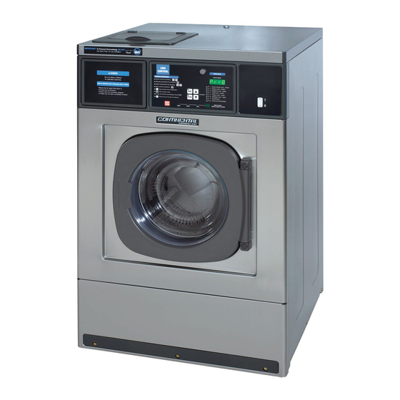
Instruction Manual for
washers
RMS6*, RMG6*,
REM*, RMG*
EN
Installation
RMS*
RMG*
REM*
Cod. 598250
Rev. 09/0918

Advertisement

Table of Contents
loading
Need help?

Need help?

Do you have a question about the RMS6 Series and is the answer not in the manual?

Questions and answers

Summary of Contents for GIRBAU RMS6 Series

  • Page 1 International sales: T.(+ 34) 938 862 219 sales@girbau.es Service: T.(+ 34) 902 300 357 sat@girbau.es www.girbau.es Installation For USA and CANADA: CONTINENTAL GIRBAU Inc. RMS* 2500 State Road 44 RMG* WI 54904 Oshkosh • USA Tel. 1(920) 231-8222 REM* info@continentalgirbau.com www.continentalgirbau.com Cod.
  • Page 2 Model From serial # RMS610 2,021,494 RMS/RMG613 2,330,000 RMS/RMG617 2,340,000 RMS/RMG623 2,350,000 RMS/RMG628 2,410,192 REM025 1,371,423 REM/RMG033 2,360,000 REM/RMG040 2,370,000 REM/RMG055 2,380,000 REM/RMG070 2,420,237 Cod. 598250 Rev. 09/0918...
  • Page 3: Table Of Contents

    Contents CONTENTS SAFETY INSTRUCTIONS ..........................3 1. TECHNICAL SPECIFICATIONS ........................7 1.1. Tools needed for installation ........................7 1.2. Accessories in machine ........................... 7 1.3. EU Declaration of conformity ........................8 1.4. Installation specifications ........................13 1.5. Electrical connection tables explanation....................16 1.6.
  • Page 4 1. The actions described in these instructions are strictly reserved for contractually AUTHORISED TECHNICAL SERVICES (ATS) and personnel who have successfully completed training by Girbau 2. The company responsible for the Authorised Technical Service accepts full liability for the work done and any possible consequences that may derive from it.
  • Page 5: Safety Instructions

    Safety instructions Disconnect the electrical connection of any circuit external to the machine; for example external dosing equipment, external vending units, folders or ironer feeders. These circuits are independent of the supply to the machine. Before beginning any procedure on machines equipped with an inverter or equipment with capacitative loads, wait for at least five minutes (10 minutes on equipment with a power rating greater than 25 kW) after the electrical disconnection, to eliminate risk of residual voltage.
  • Page 6 Safety instructions SYMBOLS USED IN MACHINE LABELLING Electrical risk High temperature risk Protective guard for elements carrying Handle with caution. an electric current. Use adequate protection. Risk of inhaling harmful or irritant Mechanical risk vapours Protective guard for moving parts. Keep the doors/covers closed.
  • Page 7: Technical Specifications

    Technical specifications 1. TECHNICAL SPECIFICATIONS 1.1. Tools needed for installation Bolting nuts M12 ........ open end or ring wrench 3/4 in (19 mm)  Bolting nuts M14 ........ open end or ring wrench 7/8 in (21 mm)  Bolting nuts M16 ........ open end or ring wrench 5/16 in (24 mm) ...
  • Page 8: Eu Declaration Of Conformity

    Technical specifications 1.3. EU Declaration of conformity RMS610 Model EU DECLARATION OF CONFORMITY Manufacturer: GIRBAU S.A. Address: Ctra. de Manlleu, km 1, 08500 Vic, Barcelona, SPAIN Identification of the machine Generic denomination: Function: Type: Washer extractor Washing in a water bath and extracting textiles Front loading Lavadora –...
  • Page 9 Technical specifications RMS613, RMG613 Model EU DECLARATION OF CONFORMITY Manufacturer: GIRBAU S.A. Address: Ctra. de Manlleu, km 1, 08500 Vic, Barcelona, SPAIN Identification of the machine Generic denomination: Function: Type: Washer extractor Washing in a water bath and extracting textiles Front loading Lavadora –...
  • Page 10 Technical specifications RMS617, RMG617 Model EU DECLARATION OF CONFORMITY Manufacturer: GIRBAU S.A. Address: Ctra. de Manlleu, km 1, 08500 Vic, Barcelona, SPAIN Identification of the machine Generic denomination: Function: Type: Washer extractor Washing in a water bath and extracting textiles Front loading Lavadora –...
  • Page 11 Technical specifications RMS623, RMG623 Model EU DECLARATION OF CONFORMITY Manufacturer: GIRBAU S.A. Address: Ctra. de Manlleu, km 1, 08500 Vic, Barcelona, SPAIN Identification of the machine Generic denomination: Function: Type: Washer extractor Washing in a water bath and extracting textiles Front loading Lavadora –...
  • Page 12 Technical specifications RMS628, RMG628 Model EU DECLARATION OF CONFORMITY Manufacturer: GIRBAU S.A. Address: Ctra. de Manlleu, km 1, 08500 Vic, Barcelona, SPAIN Identification of the machine Generic denomination: Function: Type: Washer extractor Washing in a water bath and extracting textiles Front loading Lavadora –...
  • Page 13: Installation Specifications

    Technical specifications 1.4. Installation specifications Loads and kinetic energy RMS610 RMS613 RMS617 RMS623 RMS628 UNITS REM025 REM033 REM040 REM055 REM070 DRUM VOLUME dm3 (cu. ft.) 99.1 (3.5) 125.6 (4.44) 165.6 (5.85) 225.6 (8.0) 274 (9.7) DRY LINEN CAPACITY kg 1/10 (lb) 10.1 (22.3) 12.56 (27.7) 16.56 (36.5)
  • Page 14 Technical specifications Connections RMS610 RMS/RMG613 RMS/RMG617 RMS/RMG623 RMS/RMG628 UNITS REM025 REM/RMG033 REM/RMG040 REM/RMG055 REM/RMG070 B.S.P. CONNECTION thread 2 x 3/4 2 x 3/4 2 x 3/4 2 x 3/4 2 x 3/4 (NH) mm (in) 938 (35.9) 1141 (44.9) 1141 (44.9) 1221 (48.1) 1250 (49.2) MIN/MAX...
  • Page 15 Technical specifications Images RMS610 / REM025 RMS/RMG613/17/23/28 /REM/RMG033/040/055/070 Fig. 1.1 Fig. 1.2 RMS610 / REM025 RMS/RMG613/17/23 / REM/RMG033/040/055 Fig. 1.3 Fig. 1.4 Cod. 598250 Rev. 09/0918...
  • Page 16: Electrical Connection Tables Explanation

    Technical specifications RMS/RMG628 / REM/RMG070 Fig. 1.5 1.5. Electrical connection tables explanation. Explanation and symbols of tables on sections 1.6, 1.7 and 1.8 1) HEATING 2) EXPLANATION OF WIRE VALUES Without heating Wire details in mm2 x B + N + Steam heating (USA/CANADA: wire details in AWG) x B + GND)
  • Page 17: Rms610, Rem025 Models Electrical Connection Requirements

    Technical specifications Check table explanation in section 1.5. In brackets: USA / CANADA specific values 1.6. RMS610, REM025 Models Electrical connection requirements HEATING TOTAL TOTAL SWITCH CONDUCTOR (*1) POWER CONSUMP. CURRENT (*2) VOLTAGE (AWG) 0.35 1.5 x 2 + 120V 15A mains outlet (supplied by the 1ph + N...
  • Page 18: Electrical Connection Requirements

    Technical specifications 1.7. Electrical connection requirements RMS613 / REM033 models (software version DN69 or higher) RMG613 / RMG033 models TOTAL TOTAL HEATING SWITCH CONDUCTOR POWER CONSUMP. (*1) CURRENT (*2) VOLTAGE (max) (max) (AWG) H / V 0.67/0.85 1.5 x 2 + 200V 1ph + N red.
  • Page 19 Technical specifications RMS617 / REM040 models (software version DN69 or higher) RMG617 / RMG040 models TOTAL TOTAL SWITCH CONDUCTOR HEATING (*1) POWER CONSUMP. CURRENT (*2) VOLTAGE (max) (max) (AWG) H / V 2.5 x 2 + 200V 1ph + N red.
  • Page 20 Technical specifications RMS623 / REM055 models (software version DN69 or higher) RMG623 / RMG055 models TOTAL TOTAL SWITCH CONDUCTOR HEATING (*1) POWER CONSUMP. CURRENT (*2) VOLTAGE (max) (max) (AWG) 200V 1ph + N H / V 0.93/1.05 2.5 x 2 + 208V 0.93/1.05 2.5 x 2 +...
  • Page 21 Technical specifications RMS628 / REM070 3Ph Models RMG628 / RMG070 3Ph Models TOTAL TOTAL SWITCH CONDUCTOR HEATING (*1) POWER CONSUMP. CURRENT (*2) VOLTAGE mm2 (AWG) H / V 2.5 x 3 + 200V red. 26.7 10 x 3 + norm. 14.4 41.7 25 x 3 +...
  • Page 22 Technical specifications Connection to power supply Iequ=16A Rsce=180 in accordance with UNE EN 61000-3-12:2012 RMS628 / REM070 1Ph Models RMG628 / RMG070 1Ph Models TOTAL TOTAL SWITCH CONDUCTOR HEATING (*1) POWER CONSUMP. CURRENT (*2) VOLTAGE mm2 (AWG) 200V 1ph + N H / V 2.5 x 2 + 208V...
  • Page 23: Receipt, Transport And Location

    Receipt, transport and location 2. RECEIPT, TRANSPORT AND LOCATION 2.1. Receipt The following should be checked on accepting delivery of the washer:  Check that the product has not suffered any damage in transit. (Any damage caused in this way will not be attributable to the manufacturer, and the appropriate claim should be made against the party responsible for transporting the product.) ...
  • Page 24 Receipt, transport and location Respect the ENVIRONMENTAL CONDITIONS indicated on the INSTALLATION SPECS (section 1.4). Also, respect the work and maintenance areas; these are necessary for the safe use and appropriate maintenance of the washing machine. Do not install the washer in improper vented areas. The products used can produce steam and gas products emissions, which in high concentrations can be very dangerous to health.
  • Page 25: Bolting Down

    Receipt, transport and location 2.4. Bolting down RMS610, RMS/RMG613, 617, 623 RMS/RMG628, REM/RMG070 models REM025, REM/RMG033, 040, 055 models Fig.2.1 Fig.2.2 Should the extra cardboard packing used as a spacer between the washing machine and the packaging have the holes (C) or (C and D) indicated in Fig. 2.3, this can be used as a template for the layout of the washing machine’s anchoring points on the floor.
  • Page 26: Table Of Bolting Down Values

    Receipt, transport and location 2.5. Table of bolting down values RMS/RMG628 RMS610 RMS/RMG613 RMS/RMG617 RMS/RMG623 BOLTING DOWN REM/RMG070 DIMENSIONS REM025 REM/RMG033 REM/RMG040 REM/RMG055 mm (in) 715 (28.1) 810 (31.9) 810 (31.9) 928 (36.5) 928 (36.5) A (*1) mm (in) 815 (32.0) 902 (35.5) 902 (35.5) 981 (38.6)
  • Page 27: Washer Bolting Down Systems

    Receipt, transport and location 2.6. Washer bolting down systems IMPORTANT WARNING FOR MODELS WITH A SPIN SPEED HIGHER THAN 150G. For the washer to be able to operate properly, the correct method for fastening the machine to the floor must be adopted. INCORRECT FASTENING MAY LEAD TO MAJOR FAULTS OR A SERIOUS ACCIDENT.
  • Page 28: Bolting Down Using Bolts

    Receipt, transport and location 2.6.1. Bolting down using bolts Build a concrete base according to the drawing in Figures 2.1 and 2.2 (section 2.4). The dimensions values are specified on the table in section 2.5 according to the machine model. The minimum resistance of the concrete must be equivalent to 25 N/mm2 (4000 psi).
  • Page 29: Fastening Using Metal Anchors

    Receipt, transport and location 2.6.2. Fastening using metal anchors Only RMS610 (REM025) and RMS613 (REM033) washer models with a maximum spin speed of less than 150G. THIS FASTENING SYSTEM ALLOWS IMMEDIATE USE OF THE WASHER BUT IT CAN ONLY BE APPLIED IF THE RESISTANCE OF THE FLOORING MATERIAL IS EQUAL TO OR GREATER THAN 25 N/mm2 (4000 psi) AND ITS THICKNESS IS GREATER THAN 50 mm (2 in) IN VALUE K ON FIGURE 2.6.
  • Page 30: Installing More Than One Washer

    Receipt, transport and location 2.6.3. Installing more than one washer If the installation calls for more than one washer, align them with each other. The diameter of the fastening holes makes this operation easier. The minimum distance between adjacent machines and the user and maintenance areas (values I, S and T of Figure 2.7) are specified on the table below.
  • Page 31: Safety Door Unlock (Rms/Rmg628 Models Only)

    Receipt, transport and location 2.7. Safety door unlock (RMS/RMG628 models only) To open the door in case of power failure, completely insert a rod of a diameter of 0.2 in (3 mm) and an approximate length of 4 inches (100 mm) into the bottom side of the safety lock cover, and at the same time turn the knob downwards.
  • Page 32: Installation

    Installation 3. INSTALLATION ALL CONNECTIONS FOR ELECTRICAL POWER AND PLUMBING MUST COMPLY WITH THE STATUTORY SAFETY STANDARDS APPLICABLE TO EACH COUNTRY, AND BE MADE BY AUTHORISED INSTALLATION CONTRACTORS ONLY. ALL THE WASHER CONNECTIONS MUST BE CARRIED OUT BY THE AUTHORIZED TECHNICAL SERVICE.
  • Page 33 Installation Direct connection of the washer drain to the manifold (Fig. 3.3) Facilities preferring this option to the open box option (recommended option) must respect the following precautions: Provide next to the connection point of each machine to the manifold, with a manifold ventilation outlet A reaching the outside, set at a height of 40 in (1000 mm) and of a diameter of 2 in (50 mm).
  • Page 34: Water Supply

    Installation 3.2. Water supply IMPORTANT! The local or national regulations concerning the water supply system in the country where the washing machine is installed must be followed. Hoses and pipes should be flushed through before being connected to the machine. Install at each water supply and in an accessible location, a mechanically interlocked water valve.
  • Page 35 Installation IMPORTANT 20mm dual check valve supplied with machine must be installed on the cold water inlet to the machine. This valve is designed to prevent cross connection (back siphonage) and complies with AS/NZS Standard 2845.1 (Watermark).  Fit the non-return valve A to the cold water water inlet connection of the machine considering the flow direction marked on the valve.
  • Page 36: Electrical Connection. Permanently Connected Appliances

    CONNECTED TO THE GROUND INSTALLATION WITH A CONDUCTOR CONNECTED TO THE EQUIPMENT GROUNDING TERMINAL. RMS AND REM SERIES GIRBAU WASHING MACHINES ARE DESIGNED TO OPERATE IN SINGLE- PHASE AND THREE-PHASE LINES. MODELS OF VOLTAGE BETWEEN 380 AND 415 V REQUIRE IN ADDITION A CONNECTION TO THE NEUTRAL WIRE.
  • Page 37: Machine Electrical Connection

    Installation Circuit breaker. Install an earth-leakage protected circuit breaker. Characteristics:  installed in an easily accessible place.  number of poles and intensity: consult ELECTRICAL CONNECTION table (section 1.6)  A type.  protected against pulse currents, harmonics, the presence of continuous components, etc. (consult manufacturer specifications) Safety switch.
  • Page 38 Installation RMS/RMG613, RMS/RMG617; RMS/RMG623, RMS/RMG628, REM/RMG033, REM/RMG040, REM/RMG055, REM/RMG070 models  Disconnect and mechanically lock the external automatic switch.  Open machine terminal box at the rear panel. Remove the support cover of the entry switch to the washer.  On the entry hole of the electrical supply (E identified in figure 1.4) install a lock mechanism (not supplied with the washer) to fasten the cable or cable pipe protector, depending on the cable and pipe protector used.
  • Page 39 Installation Electrical connection. 1ph, 120V units with power cord (USA / CANADA only) These models, available only for USA/CANADA installations are supplied with power cord built-in the washer. Connection characteristics These machines must be connected to an individual 15 amp branch circuit socket. Do not use any adaptor or extension cord between plug and socket.
  • Page 40: Transformer Connection. Configuring The Machine Voltage

    Installation 3.3.4. Transformer connection. Configuring the machine voltage RMS/RMG613, RMS/RMG617, RMS/RMG623 Models Disconnect and mechanically lock the external automatic switch.  Remove the support cover (A) from the junction box located on the rear panel (Fig. 3.10).  Connect the voltage selector (B) onto the transformer connector (C) in accordance with the power supply ...
  • Page 41 Installation RMS/RMG628 Models Disconnect and mechanically lock the external automatic switch.  Open the machine’s top cover.  Connect the voltage selector switch (Fig. 3.11) in accordance with the mains power supply and the following  table (Table 2). Fig. 3.11 Table 2 Mains voltage EC Connector...
  • Page 42: Steam Connection (Rms610/Rem025 Models Not Available)

    Installation 3.4. Steam connection (RMS610/REM025 models not available) In some models the body of the steam solenoid valve and the filter are shipped inside the drum of the washing machine, separate from the electrical wiring system. The coil connector is connected to the end of the electrical installation.
  • Page 43: External Dosing (Option)

    Installation 3.5. External dosing (option) The washer can communicate with external dosing equipment via electrical signals produced by the closure of relay contacts during wash cycle. These relays are mounted on the board A4, located in the electrical supply input box, at the rear of the washer. The relay contacts close the circuit between a COMMON input and the four outputs corresponding to each one of the dosing that the washer program runs.
  • Page 44: Free Voltage Relay Contact

    Installation 3.6.3. Free voltage relay contact External dosing equipment connection (Fig. 3.15) Origin of the dosing signals: external to the washer (usually from the external dosing equipment). Relay contacts from the external dosing control board act as dry contacts (not powered). Dosing signals connection on X6 terminal strip: Follow the instructions on sections 3.5.1.a &...
  • Page 45: Relay Contacts Powered From The Washer Control Circuit

    Installation 3.6.4. Relay contacts powered from the washer control circuit External dosing equipment connection (Fig. 3.16) IMPORTANT This connection allows for the maximum strength at each of the 50 mA outputs. Higher consumption can prevent the washer from functioning correctly. This connection can aggravate any problems produced by a fault in the grounding connection, both of the washer itself and of the external dosing equipment.
  • Page 46: External Dosing Electrical Connection (Rms610 / Rem025 Only)

    Installation 3.6.5. External dosing electrical connection (RMS610 / REM025 only) Signal conductor If using single-wire conductors, these must be encased within  a safety conduit. The conductor must be affixed to the inlet opening of the  machine using a secure connection appropriate for the type of conductor.
  • Page 47 Installation CAUTION! To avoid that non dissolved chemical products drip inside the washer, install the external dosing pumps (Fig. 3.19/A) and the chemical products conduction hoses (Fig. 3.19/B) below the dosing injection point (Fig. 3.19/C) to the washer. A simple bend of the conduction hoses below the level is not enough to avoid the dripping.
  • Page 48: Initial Start-Up

    Installation 3.8. Initial start-up The washer must be put into service by an AUTHORIZED TECHNICAL SERVICE. BEFORE THE STARTING-UP OF THE WASHER, BEAR IN MIND ALL THE SAFETY INSTRUCTIONS AT THE BEGINNING SECTION OF THIS MANUAL. Before the initial start-up, make sure that you accomplish the following points: ...
  • Page 49: Emergency Stop In Coin-Op Installations

    Installation 3.9. Emergency stop in coin-op installations IN ACCORDANCE WITH SAFETY REQUIREMENTS FOR INDUSTRIAL MACHINERY STANDARD (UNE- EN ISO 10472-1,5-2) AND OTHER SAFETY REQUIREMENTS, THE LAUNDRY OWNER / USER IS RESPONSIBLE FOR INSTALLING A REMOTE LOCATED EMERGENCY STOP DEVICE, CONNECTED TO EACH MACHINE.

Table of Contents