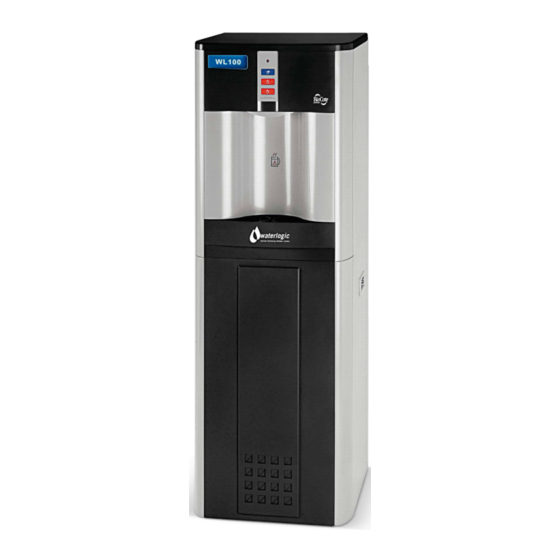
WaterLogic WL100 Technical Manual
Hide thumbs
Also See for WL100:
- Manual (70 pages) ,
- Operating, installation and service manual (65 pages) ,
- Troubleshooting manual (13 pages)
Advertisement
Table of Contents
- 1 Table of Contents
- 2 Machine Overview
- 3 Mains Parts Layout - Hot and Cold
- 4 Pre Delivery Inspection Procedures (PDI)
- 5 Installation Procedures
- 6 Operating Instructions
- 7 Maintenance and Servicing
- 8 Sanitising or Descaling
- 9 Fault Finding
- 10 Technical Specifications and Warranties
- 11 End of Life
- 12 Rohs
- 13 Biocote
- 14 Main Parts Illustration - Exploded View Diagram
- Download this manual
Advertisement
Table of Contents

Subscribe to Our Youtube Channel
Summary of Contents for WaterLogic WL100
- Page 1 WL100 Technical Manual Waterlogic 100 Technical Manual - Issue B, September 2011...
-
Page 2: Table Of Contents
Technical Specifications and Warranties End of Life ROHS BioCote® Main PBC Schematic Diagram - Hot and Cold Wetted Parts Illustration - Wetted Parts List Main Parts Illustration - Exploded View Diagram Waterlogic 100 Technical Manual - Issue B, September 2011... -
Page 3: Machine Overview
That will help inhibit lime scale formation. A Minimum flow rate of 1 litre per minute is needed for the hot tank to operate correctly. Waterlogic 100 Technical Manual - Issue B, September 2011 Waterlogic 100 Technical Manual - Issue B, September 2011... - Page 4 The valves are energized every time the customer pushes the The PCB (Printed Circuit Board) is the control unit for the WL100 which is dispense button for a drink. DC voltage is used to give a positive and quieter responsible for the functions of all the mechanical and electrical parts (24V DC).
-
Page 5: Mains Parts Layout - Hot And Cold
14. Drain the hot tank and cold tank. 15. Replace all panels, clean the machine and repack the machine. 16. Waterlogic recommend that all units are fully electrically (PAT) tested on site by the commissioning engineer as damage may have occurred during transit to the unit’s final destination. -
Page 6: Installation Procedures
This switch should only be turned on once the hot tank is filled with water. 1. Mount the WL100 on a firm flat surface with a 50mm air gap on both sides and top so that it cannot topple or fall from a counter top. - Page 7 • The filter on the WL100 must be changed every 6 months. 20. The WL100 must not be installed in direct sunlight, adjacent to a heat source, or • The cold tank should also be flushed and sanitised every 6 months.
-
Page 8: Operating Instructions
• Do not dispense water in a stop start style of vending • (Hold the button continuously until cup is full). • Never try to fill more than one vessel at a time. Waterlogic 100 Technical Manual - Issue B, September 2011... -
Page 9: Maintenance And Servicing
11. Taste the water and check the machine is clean and functions to the tank. Let the WL100 stand for a minimum of 15 minutes and then flush out the customer’s satisfaction. If you are not satisfied with the quality of the water, sanitizing solution. -
Page 10: Fault Finding
8. Clean all outside surfaces of the machine, remove and clean the WL100’s 7. Low flow of water for all circuits of the machine: Ensure that the filter is not drip tray and grill. blocked. The filter may require changing, or there is low water supply pressure. -
Page 11: Technical Specifications And Warranties
Water Connection 1/4”Hose 1/4” Hose 1/4” Hose 1/4” Hose Waterlogic has a policy of constant and continual improvement and therefore reserves the right to change specifications without prior notice, other than in Minimum Water Pressure (2.5) Bar (2.5) Bar (2.5) Bar (2.5) Bar... -
Page 12: End Of Life
Please contact your supplier/ service agent who will arrange for the collection and disposal of this product. ROHS All Waterlogic machines comply with EC Directive (2002/95/EC) on the Restriction of the Use of Certain Hazardous Substances in Electrical and Electrical Equipment (RoHS) BIOCOTE®... - Page 13 24 1/4" Blue Tube(ST) 25 5/16" X1/4"Reducing Elbow Connector(ST) 26 JG LLDPE Tube-Blue 8mm(PE-0806-100M-B) 27 1.5Liter 220V/500W Hot tank 28 Silicon Tube 5/16" for hot water 29 Silicon Tube 5/16" for hot water Waterlogic 100 Technical Manual - Issue B, September 2011...
-
Page 14: Main Parts Illustration - Exploded View Diagram
21 Front Down Insert Panel 22 Front Down Panel 23 Plastic Handel 24 Side Panel 25 Faucet HC & CA Facuet Nipple Blue Natural Faucet O-Ring (Silicon White) Stainless Steel Gauze for Faucet 18 19 Waterlogic 100 Technical Manual - Issue B, September 2011... - Page 15 34 Drip Tray Body 35 Power Transformer UV 220V/50Hz 36 Upper Base 37 Drawn Hot Tank Ass'y 1.5L 220V/50Hz 500w 38 Cold Tank Ass'y 2L 39 PCB for WL100 40 Wire Condenser Waterlogic 100 Technical Manual - Issue B, September 2011...
- Page 16 Speak to a Water Expert USA, Canada and Mexico exportsales@waterlogic.com info@waterlogicusa.com + 353 1 293 1960 + 1 402 884 7212 WLI Trading Ltd. Waterlogic USA, 4141 N. 156th Street, Suite 4, 2nd Floor Beacon Court, Omaha, NE 68116 Sandyford, Dublin 18, Ireland www.waterlogic.com...


Need help?
Do you have a question about the WL100 and is the answer not in the manual?
Questions and answers