Table of Contents
Advertisement
Quick Links
Download this manual
See also:
User Manual
®
VersaClock
3S - 5P35021 Evaluation Board
USER GUIDE
Introduction
The evaluation board is designed to help the customer evaluate the 5P35021, the latest addition to the family of programmable
devices in IDT's Timing portfolio. When the board is connected to a PC running IDT Timing Commander™ Software through
USB, the device can be configured and programmed to generate different combinations of frequencies.
Board Overview
Use
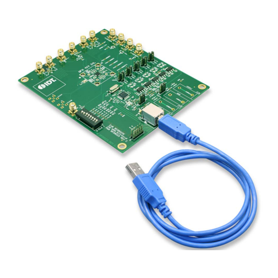
Figure 1
and
Table 1
to identify: power supply jacks, USB connector, input and output frequency SMA connectors.
Figure 1. 5P35021 Evaluation Board Overview
JULY 13, 2016
1
©2016 Integrated Device Technology, Inc.
Advertisement
Table of Contents

Related Manuals for IDT VersaClock 3S


Summary of Contents for IDT VersaClock 3S
-
Page 1: Board Overview
The evaluation board is designed to help the customer evaluate the 5P35021, the latest addition to the family of programmable devices in IDT's Timing portfolio. When the board is connected to a PC running IDT Timing Commander™ Software through USB, the device can be configured and programmed to generate different combinations of frequencies. - Page 2 Output voltage jack Connect to 3.3V core voltage of the device USB connector Connect this USB to your PC to run IDT Timing Commander DIP switch This is used to configure the device in different modes Differential clock input...
-
Page 3: Board Power Supply
® VERSACLOCK 3S - 5P35021 Evaluation Board Board Power Supply Power Supply Options The core voltage includes a digital voltage VDD33 and an analog voltage VDDA. Both core voltages can be powered by an external bench power supply or by USB. •... -
Page 4: Connecting The Board
® VERSACLOCK 3S - 5P35021 Evaluation Board Connecting the Board The board is connected to a PC through a USB connector for configuring and programming the device, as shown in Figure 4 below. The USB interface will also provide +5V power supply to the board, from which on-board voltage regulators generate various voltages for the core as well as for each output. -
Page 5: Board Default Frequency Output
® VERSACLOCK 3S - 5P35021 Evaluation Board Board Default Frequency Output Table 2: Board Default Frequency Output Serial Output Output Frequency SE_1 (Single-ended) – DIFF_CO/TO (Differential Output) 100 MHz DIFF_C1/T1 (Differential Output) 100 MHz DIP Switch (U6) Table 3: DIP Switch (U6) Serial DIP Switch Pin Number DIP Switch Pin Name... -
Page 6: Board Schematics
® VERSACLOCK 3S - 5P35021 Evaluation Board Step No. Steps Comments Once configured, new options will be available on a – green background indicating that the EVB has successfully connected with the board. Write the setting to the device by clicking on the write all registers to the chip option All intended outputs should be available for –... - Page 7 ® VERSACLOCK 3S - 5P35021 Evaluation Board Figure 6. Evaluation Board Schematic (II) Figure 7. Evaluation Board Schematic (III) JULY 13, 2016...
-
Page 8: Signal Termination Options
® VERSACLOCK 3S - 5P35021 Evaluation Board Figure 8. Evaluation Board Schematic (IV) Signal Termination Options Termination options for Differential Output 1 - 2 in the evaluation board are displayed in Figure 9. The termination circuits are designed to optionally terminate the output clocks in LVPECL, LVDS, LVCMOS and HCSL signal types by populating (or not-populating) some resistors. -
Page 9: Orderable Part Numbers
Note: ** The differential output is applicable to LPHCSL which is the default configuration of the board. * The single-ended output is applicable to LVCMOS which is the default configuration of the board. Contact IDT if user wants to change termination configuration to support other output signal types. Orderable Part Numbers The following evaluation board part numbers are available for order. - Page 10 IDT or any third parties. IDT’s products are not intended for use in applications involving extreme environmental conditions or in life support systems or similar devices where the failure or malfunction of an IDT product can be reasonably expected to significantly affect the health or safety of users.
Need help?
Do you have a question about the VersaClock 3S and is the answer not in the manual?
Questions and answers