Table of Contents
Advertisement
Quick Links
®
VersaClock
5 - 5P49V5935/33 Evaluation Boards
USER GUIDE
Introduction
The evaluation board is designed to help the customer evaluate the 5P49V5935/33, the latest addition to the family of
programmable devices in IDT's Timing portfolio. When the board is connected to a PC running IDT Timing Commander™
Software through USB, the device can be configured and programmed to generate frequencies with best-in-class performances.
Board Overview
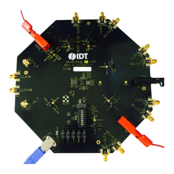
Use the following diagram to identify: power supply jacks, USB connector, input and output frequency SMA connectors.
Figure 1. Board Overview
REVISION A 05/13/15
1
©2015 Integrated Device Technology, Inc.
Advertisement
Table of Contents

Subscribe to Our Youtube Channel
Related Manuals for IDT VersaClock 5


Summary of Contents for IDT VersaClock 5
-
Page 1: Board Overview
The evaluation board is designed to help the customer evaluate the 5P49V5935/33, the latest addition to the family of programmable devices in IDT's Timing portfolio. When the board is connected to a PC running IDT Timing Commander™ Software through USB, the device can be configured and programmed to generate frequencies with best-in-class performances. -
Page 2: Board Power Supply
XIN Connector – This SMA connector is for single-ended clock input. Please note the full swing of this input is 1.2V maximum. USB connector – Used this connector to connect with your PC to run IDT Timing Commander Software. OUT1 /OUT1B – Output 1. It can be a differential pair or two individual single-ended outputs. By default, it's an LVPECL differential output. - Page 3 ® VERSACLOCK 5 - 5P49V5935/33 Evaluation Boards Figure 2. Jumping to the VDDD_J side will select external bench power supply; Jumping to the VDD_REG side will select power source from on-board regulators powered by USB • Output Clock Voltages Like VDDA and VDDD having two sources, each output voltage VDDO0~4 is also provided with two sources to choose from: bench power supply or powered from USB.
-
Page 4: Connecting The Board
® VERSACLOCK 5 - 5P49V5935/33 Evaluation Boards Connecting the Board The board is connected to a PC through a USB connector for configuring and programming the device, as shown in Figure 4 below. The USB interface will also provide +5V power supply to the board, from which on-board voltage regulators generate various voltages for the core as well as for each output. -
Page 5: Configuration And Setup
® VERSACLOCK 5 - 5P49V5935/33 Evaluation Boards Configuration and Setup The 5P49V5935/33 EVB do not need an on board crystal since it is integrated inside the device. An external clock can still be supplied to CLKIN/CLKINB connectors. The device will have two default outputs: OUT0 = 25MHz, OUT1 =100MHz when powered up. - Page 6 ® VERSACLOCK 5 - 5P49V5935/33 Evaluation Boards Figure 5. VersaClock 5 Evaluation Board Schematics – Page 1 REVISION A 05/13/15...
- Page 7 ® VERSACLOCK 5 - 5P49V5935/33 Evaluation Boards Figure 6. VersaClock 5 Evaluation Board Schematics – Page 2 REVISION A 05/13/15...
- Page 8 ® VERSACLOCK 5 - 5P49V5935/33 Evaluation Boards Figure 7. Evaluation Board Schematics – Page 3 REVISION A 05/13/15...
-
Page 9: Signal Termination Options
® VERSACLOCK 5 - 5P49V5935/33 Evaluation Boards Signal Termination Options Termination options for OUTPUT1 – 4 in the evaluation board are displayed in Figure 8. The termination circuits are designed to optionally terminate the output clocks in LVPECL, LVDS, LVCMOS and HCSL signal types by populating (or not-populating) some resistors. - Page 10 ® VERSACLOCK 5 - 5P49V5935/33 Evaluation Boards Table 1. 5P49V5933 EVB Output Termination Output Number Signal Type Series Resistors 180-ohm pull-down Series Capacitor Resistor Network R16=R20=0 OUTPUT1 LVPECL R21, R22 installed C7=C8=0.1 µF R18, R19, R23, R24 not installed R29=R32=0 ...
- Page 11 IDT or any third parties. IDT’s products are not intended for use in applications involving extreme environmental conditions or in life support systems or similar devices where the failure or malfunction of an IDT product can be reasonably expected to significantly affect the health or safety of users.
Need help?
Do you have a question about the VersaClock 5 and is the answer not in the manual?
Questions and answers