Table of Contents
Advertisement
Description
The 8Axxxx 144BGA EVK is designed to help customers evaluate
IDT ClockMatrix devices. This document discusses the following
about the EVK:
• Introduces the board and its power supply and jumper settings
• Describes the input and output connectors for normal
operation
• Explains how to bring up the board using the Timing
Commander software GUI
• Discusses how to configure and program the board to
generate standard-compliant frequencies
Kit Contents
• 8A34xxx 144BGA Evaluation Board
• USB Type A cable
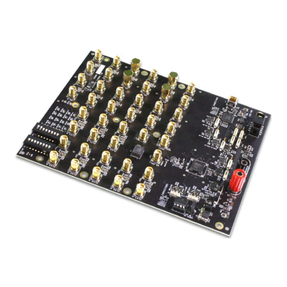
8A3xxxx 144BGA EVK Board
© 2019 Integrated Device Technology, Inc.
8A3xxxx 144BGA EVK User Manual
Requirements
• IDT Timing Commander Software Installed (available at
www.idt.com/timingcommander)
• ClockMatrix GUI (available at www.idt.com/clockmatrix)
• USB 2.0 or USB 3.0 interface
• Windows XP SP3 or later
• Processor: Minimum 1GHz
• Memory: Minimum 512MB; recommended 1GB
• Available disk space: Minimum 600MB (1.5GB 64-bit);
recommended 1GB (2GB 64-bit)
• Network access during installation if the .NET framework is not
currently installed on the system
1
February 6, 2019
Advertisement
Table of Contents

Subscribe to Our Youtube Channel
Related Manuals for IDT 8A34 Series


Summary of Contents for IDT 8A34 Series
- Page 1 8A3xxxx 144BGA EVK User Manual Description Requirements The 8Axxxx 144BGA EVK is designed to help customers evaluate • IDT Timing Commander Software Installed (available at IDT ClockMatrix devices. This document discusses the following www.idt.com/timingcommander) about the EVK: • ClockMatrix GUI (available at www.idt.com/clockmatrix) •...
-
Page 2: Table Of Contents
8A3xxxx 144BGA EVK User Manual Important Notes Disclaimer Integrated Device Technology, Inc. and its affiliated companies (herein referred to as “IDT”) shall not be liable for any damages arising out of defects resulting from delivered hardware or software (ii) non-observance of instructions contained in this manual and in any other documentation provided to user, or (iii) misuse, abuse, use under abnormal conditions, or alteration by anyone other than IDT. - Page 3 8A3xxxx 144BGA EVK User Manual List of Figures Figure 1. Overview of 144BGA ClockMatrix Evaluation Board ...........................4 Figure 2. Example of Voltage Jumpers ................................5 Figure 3. GPIO Setting and Status Display Area ..............................7 Figure 4. Board Setting for Default Operation ..............................8 Figure 5.
-
Page 4: Usage Guide
8A3xxxx 144BGA EVK User Manual 1. Usage Guide 1.1 Board Overview The following diagram identifies various components of the board: input and output SMA connectors, power supply jacks, and some jumper settings necessary for the board operations. Figure 1. Overview of 144BGA ClockMatrix Evaluation Board Detailed descriptions of the board are as follows. -
Page 5: Board Power Supply
8A3xxxx 144BGA EVK User Manual • VCCO voltage selection jumpers – Each output voltage can be individually supplied with 1.8V, 2.5V, or 3.3V. These jumpers are used to select the voltage for the output voltages. • Reset button – A small button is used to reset the board. •... -
Page 6: Gpio Switches, Leds, And Test Points
8A3xxxx 144BGA EVK User Manual The following list shows which head/jumper is used to select what voltage: • JP1 – VDDD • JP2 – VDDA • JP3 – VCC_GPIO_DC • JP4 – VDDO_Q8_3_5 • JP5 – VDDO_Q2_4_11 • JP6 – VDDO_1_10_7 •... -
Page 7: Usb Jack
8A3xxxx 144BGA EVK User Manual Figure 3. GPIO Setting and Status Display Area 1.5 USB Jack The board has a USB mini-connector. The other end of the USB cable is a USB Type A connector going to a PC. 1.6 Onboard EEPROM An onboard EEPROM is used to store device firmware and/or customer’s configuration data. -
Page 8: Working With Timing Commander™ For Programing/Configuration
The board can operate off an EEPROM that has stored all information including firmware and a default configuration data. A default operation provides a sanity check on the board before running the board through the IDT Timing Commander. Please set the board in the following default conditions (see Figure 4 for jumper and switch positions). -
Page 9: Using Timing Commander To Control The Board
8A3xxxx 144BGA EVK User Manual 2.2 Using Timing Commander to Control the Board Once the default operation is successful, complete the following steps to configure and program the ClockMatrix device per your specific application requirements using Timing Commander GUI tools: 1. -
Page 10: Figure 6. Selecting 8A34001 Using Personality File V4.6
8A3xxxx 144BGA EVK User Manual 3. After selecting “New Settings File”, a device selection window will pop up. In the window, choose the intended device in the list (in this example, 8A34001 is selected). Click the button at the lower right corner of the window (red circle) to browse and select the correct personality file (in this example, personality v4.6 is selected). -
Page 11: Figure 7. Timing Commander Gui With A Settings File Opened
8A3xxxx 144BGA EVK User Manual 4. The GUI window with the 8A34001 block diagram will open for configurations; or if “Open Settings File” is selected in Step 3, you will be prompted to browse and select an existing .tcs file and the personality file. When the configuration file is open, all configured values will be displayed (see Figure 7). -
Page 12: Figure 8. Setting I 2 C For Connecting The Board With Gui
8A3xxxx 144BGA EVK User Manual 5. In order to connect the board with Timing Commander (PC), click the button (red circle) at the up-right corner of the GUI to set up the communication protocols (see Figure 7). After I C and one-byte addressing are selected, click OK to close the window. Figure 8. -
Page 13: Figure 10. Firmware Version Mismatch Warning Message
8A3xxxx 144BGA EVK User Manual 7. If ClockMatrix chip’s firmware, or firmware loaded from EEPROM, has a different version from that in the Personality file, a firmware version mismatch warning message will appear. Click “Close” button to close the message window and a connection is made. Figure 10. -
Page 14: Figure 12. Read Firmware Version Of Clockmatrix Chip
8A3xxxx 144BGA EVK User Manual 9. Within the Firmware Utility window, click the “Get Firmware Version” button to read the firmware version. Figure 12. Read Firmware Version of ClockMatrix Chip 10. In the case where the firmware version mismatches each other, a firmware upgrade is necessary to update the chip’s firmware. To do so, complete the steps in How to Upgrade the Firmware to update the chip’s firmware. -
Page 15: Output Terminations And Rework To Take 1Pps Input
8A3xxxx 144BGA EVK User Manual 2.3 Output Terminations and Rework to Take 1PPS Input All outputs are terminated with a 100Ω resistor across the output pair. This is the recommended termination regardless of the Voffset and Vswing settings. Since the outputs are DC-coupled, they will support a 1PPS output without any need for rework. Important Equipment Warning: When connecting the outputs to measurement equipment, use a DC-block to ensure... -
Page 16: How To Upgrade The Firmware
8A3xxxx 144BGA EVK User Manual 3. How to Upgrade the Firmware 3.1 Upload Firmware to the RAM 1. Connect to the EVK board. 2. Power up the board with no EEPROM present. This ensures the firmware is 4.0.2.7017, as displayed in the figure. 3. - Page 17 8A3xxxx 144BGA EVK User Manual In the next window, press “Yes” and wait around 3-4 minutes. Once the firmware is updated, the following window will indicate a successful update. Click “Close”. Press “Get Firmware Version” to verify that the RAM was updated correctly, then click “Close”. ©...
-
Page 18: Upload Firmware Into The Eeprom
8A3xxxx 144BGA EVK User Manual 3.2 Upload Firmware into the EEPROM 1. Once the firmware has been updated to the chip (steps 1 to 8), install the EEPROM on the EVK board. 2. Press “Write Firmware to EEPROM Only”. 3. In the next window, press “Yes”. ©... -
Page 19: Verify The Eeprom Programming
8A3xxxx 144BGA EVK User Manual 4. When asked to “Verify” the EEPROM, press “No”. 5. In the next window, press “Close” to start the EEPROM write. 6. Wait about 5 minutes for the EEPROM write to complete. Click “Close” in the following window. 3.3 Verify the EEPROM Programming 7. -
Page 20: Schematics
8A3xxxx 144BGA EVK User Manual 4. Schematics © 2019 Integrated Device Technology, Inc. February 6, 2019... - Page 21 8A3xxxx 144BGA EVK User Manual © 2019 Integrated Device Technology, Inc. February 6, 2019...
- Page 22 8A3xxxx 144BGA EVK User Manual © 2019 Integrated Device Technology, Inc. February 6, 2019...
- Page 23 8A3xxxx 144BGA EVK User Manual © 2019 Integrated Device Technology, Inc. February 6, 2019...
- Page 24 8A3xxxx 144BGA EVK User Manual © 2019 Integrated Device Technology, Inc. February 6, 2019...
- Page 25 8A3xxxx 144BGA EVK User Manual © 2019 Integrated Device Technology, Inc. February 6, 2019...
- Page 26 8A3xxxx 144BGA EVK User Manual © 2019 Integrated Device Technology, Inc. February 6, 2019...
- Page 27 8A3xxxx 144BGA EVK User Manual © 2019 Integrated Device Technology, Inc. February 6, 2019...
- Page 28 8A3xxxx 144BGA EVK User Manual © 2019 Integrated Device Technology, Inc. February 6, 2019...
-
Page 29: Ordering Information
IDT's products are not intended for use in applications involving extreme environmental conditions or in life support systems or similar devices where the failure or malfunction of an IDT product can be reasonably expected to significantly affect the health or safety of users. Anyone using an IDT product in such a manner does so at their own risk, absent an express, written agreement by IDT.
Need help?
Do you have a question about the 8A34 Series and is the answer not in the manual?
Questions and answers