Table of Contents
Advertisement
Description
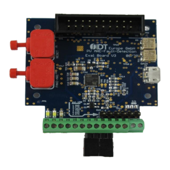
The ZNRG2061 Evaluation Kit is designed to help the user
evaluate IDT's ZNRG2061 Smart Photovoltaic DC Arc-Fault
Detector IC. The kit includes the ZNRG2061 Evaluation Board
with a sample ZNRG2061 mounted, a current transformer, and a
micro-USB cable for connecting the kit to the user's computer.
When the Evaluation Board is connected to the user's computer
via a USB port, the ZNRG2061 can be monitored for arc-fault
detection. A test arc circuit enables self-testing of the device.
IDT's ZNRG2061 Arc Analyzer Software provides a graphical
user interface (GUI) to enable configuration, data analysis, and
communication with the ZNRG2061 mounted on the Evaluation
Board. The GUI is also used to activate the training sequence that
allows the ZNRG2061 to adapt its algorithms for safe and reliable
detection of arc faults The GUI is available for download on IDT's
website.
ZNRG2061 Evaluation Kit
© 2017 Integrated Device Technology, Inc.
ZNRG2061 Evaluation Kit User Manual
Features
Complete system demonstrates ZNRG2061 arc-detection
performance
Evaluation Board includes arc test circuitry
Current transformer is included for easy evaluation
The kit can derive its power from the USB connection so no
additional power supply is required
To ensure use of the latest version, the ZNRG2061 Evaluation
Software and the ZNRG2061 Evaluation Software User Guide
are available for download on
Kit Contents
ZNRG2061 Evaluation Board, Revision V 3.0
100:100-Turns Current Transformer
Micro-USB cable
1
www.IDT.com/ZNRG2061-EVK
March 29, 2017
Advertisement
Table of Contents

Subscribe to Our Youtube Channel
Related Manuals for IDT ZNRG2061


Summary of Contents for IDT ZNRG2061
-
Page 1: Kit Contents
When the Evaluation Board is connected to the user’s computer additional power supply is required via a USB port, the ZNRG2061 can be monitored for arc-fault To ensure use of the latest version, the ZNRG2061 Evaluation detection. A test arc circuit enables self-testing of the device. -
Page 2: Important Notes
ZNRG2061 Evaluation Kit User Manual Important Notes Disclaimer Integrated Device Technology, Inc. and its affiliated companies (herein referred to as “IDT”) shall not be liable for any damages arising out of defects resulting from delivered hardware or software (ii) non-observance of instructions contained in this manual and in any other documentation provided to user, or (iii) misuse, abuse, use under abnormal conditions, or alteration by anyone other than IDT. -
Page 3: Computer Requirements
1.2.2 Software Installation and Setup To ensure use of the latest version of the software, the ZNRG2061 Arc Analyzer Software zip file is available for download in zip file format at no cost from the IDT web site page given on page 1. It is not included with the kit hardware. - Page 4 Initial Display after Installation of the Evaluation Software Note: This is the display when the software is activated for the first time with the kit hardware connected. Refer to the ZNRG2061 Software User Manual for the initial setup steps for the software.
-
Page 5: Kit Hardware Connections
ZNRG2061 Evaluation Kit User Manual Kit Hardware Connections Set up the Evaluation Kit connections as shown in Figure 2. Refer to Table 1 below for the description. Figure 2. ZNRG2061 Evaluation Board Overview Table 1. Evaluation Board Key Components and Functions Note: See Figure 2 for the number references used in this table. - Page 6 ZNRG2061 Evaluation Kit User Manual Ref. Name Connector Label Function AFD (X2-5 on X2) Arc-fault detection output. It is indicated by the AFD LED on board. See Figure 4. AFS (X2-4 on X2) Arc feature signal output; it is indicated by the AFS LED on board. See Figure 4.
- Page 7 ZNRG2061 Evaluation Kit User Manual Power-up After installing the GUI as described in section 1.2.2 and setting up the kit hardware as described in section1.3, use the micro-USB cable to connect the USB connector to an available USB port on the user’s computer as shown in Figure 4. Then activate the GUI to control the Evaluation Board.
-
Page 8: Usage Guide
If the final recovery attempt is not successful, the AFD pin will be set HIGH. If set, the AFD pin is permanently latched HIGH, and the ZNRG2061 will not reset the output by itself. Only a power off/on cycle or a GUI command can reset this pin. - Page 9 The Evaluation Kit has been pre-tested with the right values for potentiometers R3 and R11. Refer to the ZNRG2061 Software User Manual for full details for using the arc fault detector test circuit with the GUI.
-
Page 10: Evaluation Board Schematic
ZNRG2061 Evaluation Kit User Manual Evaluation Board Schematic Figure 8. Evaluation Board – Main Circuit © 2017 Integrated Device Technology, Inc. March 29, 2017... - Page 11 ZNRG2061 Evaluation Kit User Manual Figure 9. Evaluation Board Schematic – USB Circuit © 2017 Integrated Device Technology, Inc. March 29, 2017...
-
Page 12: Bill Of Materials (Bom)
ZNRG2061 Evaluation Kit User Manual Bill of Materials (BOM) The parts with an (*) are not populated. Table 2. Evaluation Board BOM Name Value Package Manufacturer KP-2012SURC 0805 Kingbright AFS, POWER LTW-170ZDC 0805 Lite-On C1, C2, C4, C5, C6*, C15, C23, C24,... - Page 13 ZNRG2061 Evaluation Kit User Manual Name Value Package Manufacturer 0603 Yageo 0603 Yageo 0603 Yageo R7, R40 0603 Yageo R8, R9, R20, R21, R22, R23, R24, 0603 Yageo R42, R43 R10, R36, R37 0603 Yageo Bourns R12, R13 0603 Yageo...
-
Page 14: Board Layout
ZNRG2061 Evaluation Kit User Manual Board Layout Figure 10. ZNRG2061 Evaluation Board V3.0 Board Layout – Top Assembly Layer with Silkscreen © 2017 Integrated Device Technology, Inc. March 29, 2017... - Page 15 ZNRG2061 Evaluation Kit User Manual Figure 11. ZNRG2061 Evaluation Board V3.0 Board Layout – Top Layer © 2017 Integrated Device Technology, Inc. March 29, 2017...
- Page 16 ZNRG2061 Evaluation Kit User Manual Figure 12. ZNRG2061 Evaluation Board V3.0 Board Layout – Bottom Layer © 2017 Integrated Device Technology, Inc. March 29, 2017...
- Page 17 ZNRG2061 Evaluation Kit User Manual Figure 13. ZNRG2061 Evaluation Board V3.0 Board Layout – Bottom Assembly and Silkscreen © 2017 Integrated Device Technology, Inc. March 29, 2017...
-
Page 18: Ordering Information
IDT's products are not intended for use in applications involving extreme environmental conditions or in life support systems or similar devices where the failure or malfunction of an IDT product can be reasonably expected to significantly affect the health or safety of users. Anyone using an IDT product in such a manner does so at their own r isk, absent an express, written agreement by IDT.
Need help?
Do you have a question about the ZNRG2061 and is the answer not in the manual?
Questions and answers