Table of Contents
Advertisement
Quick Links
Description
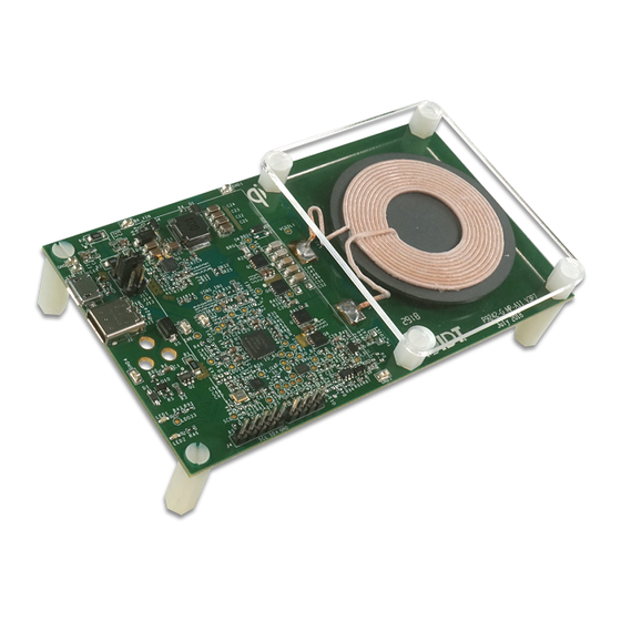
The P9242-G-EVK Evaluation Board demonstrates the features of
the P9242-G 15W Wireless Power Transmitter (TX) with a fixed
frequency. It is intended to evaluate the functionality and
performance of the P9242-G when combined with a Qi power
receiver in a wireless charging system. The P9242-G-EVK offers
the flexibility to select parameters, such as Q-factor threshold, LED
pattern, power loss FOD threshold, and external temperature
sensing function. The printed circuit board (PCB) has four layers. It
can be used with the user's WPC-1.2.4 compliant receiver.
The high-efficiency, turnkey reference design is supported by
comprehensive online, digital resources to significantly expedite
the design-in effort and enable rapid prototyping.
Kit Contents
P9242-G-EVK Evaluation Board
Adaptor: 18V/1.38A
P9242-G-EVK Mass-Market Evaluation Board
© 2019 Integrated Device Technology, Inc.
P9242-G-EVK Evaluation Board User Manual
Features
P9242-G Evaluation Board with support for WPC-1.2.4
Up to 15W output power
Adjustable open Q-factor threshold
Adjustable power loss FOD threshold
Adjustable temperature shutdown
Two programmable LED status indicators
Four-layer PCB
Fully assembled with test points and coil fixture
12V/1.38A AC Adapter (Not to scale)
1
February 17, 2019
Advertisement
Table of Contents

Subscribe to Our Youtube Channel
Related Manuals for IDT P9242-G-EVK


Summary of Contents for IDT P9242-G-EVK
- Page 1 Adjustable open Q-factor threshold performance of the P9242-G when combined with a Qi power Adjustable power loss FOD threshold receiver in a wireless charging system. The P9242-G-EVK offers the flexibility to select parameters, such as Q-factor threshold, LED Adjustable temperature shutdown pattern, power loss FOD threshold, and external temperature ...
-
Page 2: Table Of Contents
OF TRADE, CUSTOM, OR COURSE OF DEALING. Restrictions in Use IDT’s [Kit Name], consisting of the [Kit Contents and Software], is designed for [list of intended purposes] only. IDT’s [Kit Name and Software] must not be used for [list of prohibited uses]. - Page 3 P9242-G-EVK Evaluation Board User Manual List of Figures Figure 1. P9242-G V3.8 Evaluation Board Features ............................15 Figure 2. P9242-G V3.8 Evaluation Board Detail .............................16 Figure 3. R61 and R62 Schematic Location ..............................17 Figure 4. R61 and R62 PCB Location................................18 Figure 5. TH_COIL1, R60, and RC67 Schematic Location ..........................18 Figure 6.
-
Page 4: Hardware Setup
Tx Coil Input Select Jumpers Vin Power Connector: Micro-USB Vin Connector: USB-C Vin Power Connector: Barrel Green LED and Red LED J5 IDT-Reserved Connector – Do Not Use J4 I2C Connector © 2018 Integrated Device Technology, Inc. February 17, 2019... -
Page 5: Led Pattern Selection
LED Pattern Selection The P9242-G-EVK uses two LEDs (LED1 and LED2; see Figure 1) to indicate the power transfer status, faults, and operating modes. The LEDs are connected to the LED1 and LED2 pins as shown in the P9242-G-EVK schematics. -
Page 6: Figure 3. R61 And R62 Schematic Location
P9242-G-EVK Evaluation Board User Manual Table 1. LED Pattern Selection Status Option Voltage on GPIO_A3 Pin LED1/LED2 Pin Standby Transfer Complete Fault 0V ≤ V < 0.1V; GPIO_A3 LED2 0.7V < V < 0.8V; GPIO_A3 1.4V < V < 1.5V;... -
Page 7: External Temperature Sensing (Ts)
P9242-G-EVK Evaluation Board User Manual Figure 4. R61 and R62 PCB Location External Temperature Sensing (TS) The P9242-G includes an optional temperature sense input pin, TS, that is used to monitor a remote temperature, such as for a coil or a battery charger. -
Page 8: External Buck Regulator
External Buck Regulator To operate at a fixed 127.7kHz frequency, the P9242-G-EVK has adopted an MP2229 Buck IC to adjust the power transfer between the transmitter and receiver. GPIO_A4 and GPIO_B4 are assigned to adjust the MP2229 FB control. The MP2229 is operating at a fixed 500kHz frequency on the board. -
Page 9: Bypass Path Of The External Buck Regulator
Bypass Path of the External Buck Regulator When the adaptor voltage is 5V only (such as USB DCP or legacy USB 5V adaptors), the P9242-G-EVK supports such adaptors by turning off the Buck regulator, and then enable a bypass path. The P9242-G will be operating in a variable frequency mode, to adjust the total power transferred. -
Page 10: External Oscillator
P9242-G-EVK Evaluation Board User Manual Figure 10. Buck Regulator PCB Location External Oscillator To guarantee that the switching frequency is fixed at an accurate 127.7kHz ±6Hz, an external clock IC and a crystal is used to guarantee that the frequency will be in the range displayed in Table 2. The frequency of the clock IC or MEMS oscillator must be precisely 6.16791MHz to work with the P9242-G. -
Page 11: Resonant Capacitor
Figure 12. Buck Regulator PCB Location Resonant Capacitor The P9242-G-EVK uses multi-layer ceramic capacitors as the resonant caps. A combination of 100nF/250V/X7R/1206 capacitors and 100nF/100V//C0G/1206 capacitors are used. If class II ceramic capacitors are used as the resonant capacitors, they need to be carefully selected. -
Page 12: Q-Factor Detection And Open Advanced Q-Factor
P9242-G-EVK Evaluation Board User Manual Q-factor Detection and Open Advanced Q-factor The P9242-G-EVK has implemented the Q-factor detection for WPC EPP receivers. The Q_DEC pin is used to sample the voltage on the coil. Figure 13 shows the Q-factor detection circuits. -
Page 13: Figure 14. Q-Factor Pcb Location
P9242-G-EVK Evaluation Board User Manual Figure 14. Q-factor PCB Location Table 3 shows how to set up the Advanced Q-factor threshold. Table 3. Voltage on GPIO_A2 vs. Advanced Q-factor Threshold Voltage on GPIO_A2 Advanced Open Q-Factor Threshold 0V ≤ VGPIO_A2 < 0.4V Feature Disabled 0.4V <... -
Page 14: Selection Of Input Source And Operation Mode
2.3V < VGPIO_A2 < 2.4V Selection of Input Source and Operation Mode The P9242-G-EVK supports different types of AD/DC adaptors and connectors. By selecting the jumpers in Figure 15, you can select the USB- Micro connector, USB-C connector, or DC jack adaptor. -
Page 15: Transmitter Coil
P9242-G-EVK Evaluation Board User Manual The P9242-G-EVK supports a wide range of input DC sources from 5V to 19V. Based on the input source, the P9242-G-EVK supports different types of receivers. Table 4 lists the P9242-G-EVK operation modes. Table 4. -
Page 16: P9242-G Evaluation Board Schematic
P9242-G-EVK Evaluation Board User Manual 3. P9242-G Evaluation Board Schematic © 2018 Integrated Device Technology, Inc. February 17, 2019... -
Page 17: Bill Of Materials (Bom)
P9242-G-EVK Evaluation Board User Manual 4. Bill of Materials (BOM) Table 3. P9242-G-EVK BOM Item Quantity Reference Value Description Part Number Footprint VIN1,GND1,GND2,GND3,GND4, TEST POINT PC MINIATURE test_pt_sm_ 5015 BK_VIN,VIN_SEL,GND 135x70 V_BRIDGE1,VSNS_IN1,VDEM1, VCOIL1,SW_BRG1,IO_B1,ENB1, CSP1,CSN1,BRG1_LG,BRG1_H G,SW_BRG2,IO_B2,IO_A2,BRG2 TEST_PT30 _LG,BRG2_HG,IO_B3,IO_A3,IO_ 30 GAUGE WIRE PAD... - Page 18 P9242-G-EVK Evaluation Board User Manual Item Quantity Reference Value Description Part Number Footprint C1005X5R1E105M0 C37,C43,C50,C53 CAP CER 1uF 25V X5R 0402 50BC GCM188R71H223K C39,C59 22nF CAP CER 22nF 50V X7R 0603 A37D GRM31C5C2A104J C44,C47, 100nF CAP CER 100nF 100V C0G 1206...
- Page 19 P9242-G-EVK Evaluation Board User Manual Item Quantity Reference Value Description Part Number Footprint SIA453EDJ- Powerdi333 MOSFET P-CH 30V SIA453EDJ-T1-GE3 T1_GE3 3_8ld_fet Si3417 MOSFET P-CH 30 V Si3417DV-T1-GE3 SOT-23-6 Q4,Q9 2N7002 MOSFET N-CH 60V 2N7002KT1G SOT23_3 DMG7430L powerdi333 Q5,Q6,Q7,Q8 MOSFET N-CH 30V...
- Page 20 P9242-G-EVK Evaluation Board User Manual Item Quantity Reference Value Description Part Number Footprint R24,R33,R34,R37,R38,R51,R56, R66,R71,R72,R75,R78,R79,R84, R85,R89,R91,R92,R94 RES SMD 0.02 OHM 1% 1/3W 0.02 UCR10EVHFSR020 0805 RES SMD 51K OHM 1% 1/16W RC0402FR-0751K 0402 RES SMD 510 OHM 1% 1/16W RC0402FR-...
-
Page 21: Board Layout
P9242-G-EVK Evaluation Board User Manual 5. Board Layout Figure 16. Silkscreen – Top of Board © 2018 Integrated Device Technology, Inc. February 17, 2019... -
Page 22: Figure 17. Copper - Top Layer
P9242-G-EVK Evaluation Board User Manual Figure 17. Copper – Top Layer Figure 18. Copper L1 Layer © 2018 Integrated Device Technology, Inc. February 17, 2019... -
Page 23: Figure 19. Copper L2 Layer
P9242-G-EVK Evaluation Board User Manual Figure 19. Copper L2 Layer Figure 20. Copper Bottom © 2018 Integrated Device Technology, Inc. February 17, 2019... -
Page 24: Ordering Information
The information contained herein is provided without representation or warranty of a ny kind, whether express or implied, including, but not limited to, the suitability of IDT's products for any particular purpose, an implied warranty of merchantability, or non -infringement of the intellectual property rights of others. This document is presented only as a guide and does not convey any license under intellectual property rights of IDT or any third parties.
Need help?
Do you have a question about the P9242-G-EVK and is the answer not in the manual?
Questions and answers