Table of Contents
Advertisement
Quick Links
Fluidcontrol
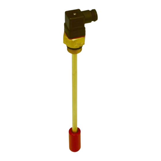
Level switch for tank installation
NT M...-Atex
Installation and Operation Instructions
Original instructions
BE100011
Bühler Technologies GmbH, Harkortstr. 29, D-40880 Ratingen
03/2018
Tel. +49 (0) 21 02 / 49 89-0, Fax: +49 (0) 21 02 / 49 89-20
E-Mail: fluidcontrol@buehler-technologies.com
Internet: www.buehler-technologies.com
Advertisement
Table of Contents

Related Manuals for Bühler technologies NT Mx-Atex Series


Summary of Contents for Bühler technologies NT Mx-Atex Series
- Page 1 Fluidcontrol Level switch for tank installation NT M...-Atex Installation and Operation Instructions Original instructions BE100011 Bühler Technologies GmbH, Harkortstr. 29, D-40880 Ratingen 03/2018 Tel. +49 (0) 21 02 / 49 89-0, Fax: +49 (0) 21 02 / 49 89-20 E-Mail: fluidcontrol@buehler-technologies.com Internet: www.buehler-technologies.com...
- Page 2 Bühler Technologies GmbH, Harkortstr. 29, D-40880 Ratingen Tel. +49 (0) 21 02 / 49 89-0, Fax: +49 (0) 21 02 / 49 89-20 Internet: www.buehler-technologies.com E-Mail: fluidcontrol@buehler-technologies.com Read this instruction carefully prior to installation and/or use. Pay at- tention particularly to all advises and safety instructions to prevent in- juries.
-
Page 3: Table Of Contents
NT M...-Atex Contents Introduction............................................. 2 Intended Use......................................... 2 Layout and Functionality .................................... 2 Scope of Delivery........................................ 2 Type plate .......................................... 2 Model Key .......................................... 3 Safety instructions......................................... 4 Important advice ......................................... 4 General hazard warnings .................................... 5 Transport and storage ........................................ 6 4 Installation and connection ...................................... -
Page 4: Introduction
NT M...-Atex 1 Introduction 1.1 Intended Use The level switches are used to monitor levels and temperatures inside a tank. The measuring tube is inside the tank during the process. According to EN 60079-11, NT M…-Atex series level switches are simple electrical apparatuses without separate voltage source in- tended for tank top installation. -
Page 5: Model Key
NT M...-Atex 1.5 Model Key XX XX XX XX XX NT M ATEX Type designation Options Version = oval flange (for G3/4) = adapter G3/4 to G1 Pt100 = temperature sensor Connection G3/4 Temperature contact NC contact NO contact Plug * TM50NC TM50NO = 50 °C... -
Page 6: Safety Instructions
NT M...-Atex 2 Safety instructions 2.1 Important advice This unit may only be used if: – The product is being used under the conditions described in the operating- and system instructions, used according to the nameplate and for applications for which it is intended. Any unauthorized modifications of the device will void the warranty provided by Bühler Technologies GmbH, –... -
Page 7: General Hazard Warnings
NT M...-Atex 2.2 General hazard warnings The equipment must be installed by a professional familiar with the safety requirements and risks. Be sure to observe the safety regulations and generally applicable rules of technology relevant for the installation site. Prevent malfunctions and avoid personal injuries and property damage. -
Page 8: Transport And Storage
NT M...-Atex 3 Transport and storage Only transport the product inside the original packaging or a suitable alternative. The equipment must be protected from moisture and heat when not in use. It must be stored in a covered, dry, dust-free room at room temperature. -
Page 9: Installation And Connection
NT M...-Atex 4 Installation and connection 4.1 Installation Please note before installing the level switch! After transport and delivery of the level switch, the switching status of the bistable contacts may be different than required for proper operation. Therefore slide the float for the level switch along the level switch tube from below immediately before installation. This ensures all built-in bistable contacts have a clearly defined switching status (NC or NO). -
Page 10: Intrinsically-Safe Connection
NT M...-Atex PA connection example: Drawing A 1 Temperature switch TSK-Atex 5 PA cable 2 PA decal 6 PA connection on the tank 3 PA connection on the temperature switch 7 Tank 4.2.2 Intrinsically-safe connection According to EN 60079-11 the components for level and temperature monitoring are simple electrical equipment and to be con- sidered purely ohmic circuits. -
Page 11: Operation And Control
NT M...-Atex 5 Operation and control DANGER Toxic, acidic gases/liquids Protect yourself from toxic, corrosive gasses/liquids when performing any type of work. Wear appropriate protective equipment. DANGER Dangerous electrostatic charge (explosion hazard) The equipment may only be used where normal operating conditions do not produce frequent flammable, electrostatic discharge. - Page 12 NT M...-Atex Level display: Inside the float of a level switch is a magnet which is mounted in a way that exceeding the level contacts (bistable reed contacts) will trigger these magnetically. This can switch signals used to display the liquid level. When using several level contacts inside the level switch, signals are switched using a common root.
-
Page 13: Cleaning And Maintenance
NT M...-Atex 6 Cleaning and Maintenance This device is maintenance-free. The method for cleaning the devices must be adapted to the IP protection class of the devices. Do not use cleaners which could damage the device materials. BE100011 ◦ 03/2018 Bühler Technologies GmbH... -
Page 14: Service And Repair
NT M...-Atex 7 Service and repair This chapter contains information on troubleshooting and correction should an error occur during operation. Repairs to the unit must be performed by Bühler authorised personnel. Please contact our Service Department with any questions: Tel.: +49-(0)2102-498955 or your agent If the equipment is not functioning properly after correcting any malfunctions and switching on the power, it must be inspected by the manufacturer. -
Page 15: Disposal
NT M...-Atex 8 Disposal Dispose of parts so as not to endanger the health or environment. Follow the laws in the country of use for disposing of elec- tronic components and devices during disposal. BE100011 ◦ 03/2018 Bühler Technologies GmbH... -
Page 16: Appendices
NT M...-Atex 9 Appendices 9.1 Technical Data NT M…-Atex Dimensions Operating pressure: max. 1 bar PA connection Operating temperature: max. +80 °C Ambient temperature: -20 to +80 °C Fluid density: min. 0.8 kg/dm SW 36 Material Switching tube: Brass 1.4571 Flange: Brass 1.4571... -
Page 17: Standard Pin Assignment
NT M...-Atex Plug connection M12 (base) Dimensions: Number of pins: 3-pin + PE 4-pin+PE DIN EN: 175301-803 IP rating: IP 65 IP 67** Cable fitting: PG 11 Max. number of contacts Level/temperature contact 1 x K8/1 x TM 1 x K8/1 x TM Level contact only 2 x K8 2 x K8... -
Page 18: Definitions
NT M...-Atex 9.3 Definitions The contact positions are measured top to bottom: L1 = Contact no. 1 L2 = Contact no. 2 L3 = Contact no. 3 , etc. Note: The number of contacts may be limited depending on the level switch model (see model key in the type plate and technical data). -
Page 19: Attached Documents
NT M...-Atex 10 Attached documents – Manufacturer Declaration HX100001 – RMA - Decontamination Statement BE100011 ◦ 03/2018 Bühler Technologies GmbH... - Page 21 RMA - Dekontaminierungserklärung RMA - Decontamination Statement DE/EN Gültig ab / valid since: 2014/11/01 Revision / Revision 1 ersetzt Rev. / replaces Rev. 0 Um eine schnelle und reibungslose Bearbeitung Ihres Anlie- Please complete this return form to ensure your claim is gens zu erreichen, füllen Sie bitte diesen Rücksendeschein processed quickly and efficiently.
- Page 22 RMA - Dekontaminierungserklärung RMA - Decontamination Statement DE/EN Gültig ab / valid since: 2014/11/01 Revision / Revision 1 ersetzt Rev. / replaces Rev. 0 Bitte füllen Sie diese Dekontaminierungserklärung für jedes Please complete this decontamination statement for each einzelne Gerät aus. individual item Gerät / Device RMA-Nr /...
Need help?
Do you have a question about the NT Mx-Atex Series and is the answer not in the manual?
Questions and answers