Table of Contents
Advertisement
Quick Links
Fluidcontrol
External level switches
NS xx/xx-AM, HD-NS xx-AM
Installation and Operation Instructions
Original instructions
BE200001
Bühler Technologies GmbH, Harkortstr. 29, D-40880 Ratingen
08/2020
Tel. +49 (0) 21 02 / 49 89-0, Fax: +49 (0) 21 02 / 49 89-20
E-Mail: fluidcontrol@buehler-technologies.com
Internet: www.buehler-technologies.com
Advertisement
Table of Contents

Subscribe to Our Youtube Channel
Related Manuals for Bühler technologies IO-Link NS AM Series


Summary of Contents for Bühler technologies IO-Link NS AM Series
- Page 1 Fluidcontrol External level switches NS xx/xx-AM, HD-NS xx-AM Installation and Operation Instructions Original instructions BE200001 Bühler Technologies GmbH, Harkortstr. 29, D-40880 Ratingen 08/2020 Tel. +49 (0) 21 02 / 49 89-0, Fax: +49 (0) 21 02 / 49 89-20 E-Mail: fluidcontrol@buehler-technologies.com Internet: www.buehler-technologies.com...
- Page 2 Bühler Technologies GmbH, Harkortstr. 29, D-40880 Ratingen Tel. +49 (0) 21 02 / 49 89-0, Fax: +49 (0) 21 02 / 49 89-20 Internet: www.buehler-technologies.com E-Mail: fluidcontrol@buehler-technologies.com Read this instruction carefully prior to installation and/or use. Pay at- tention particularly to all advises and safety instructions to prevent in- juries.
-
Page 3: Table Of Contents
NS xx/xx-AM, HD-NS xx-AM Contents Introduction............................................. 2 Intended Use......................................... 2 Functionality......................................... 2 1.2.1 Liquid level monitoring .................................. 2 Model key NS 10 ........................................ 2 Model key NS 25 ........................................ 2 Model key NS 64........................................ 3 Model key NS 100......................................... 3 Model key HD NS 250...................................... 3 Model key HD NS 360 ...................................... -
Page 4: Introduction
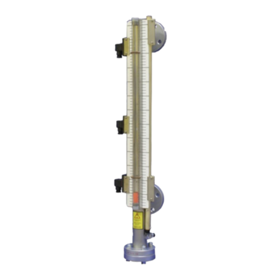
NS xx/xx-AM, HD-NS xx-AM 1 Introduction 1.1 Intended Use The level switches are used to monitor the liquid level in fluid systems. They mount to the outside of the tank and have a visual display and electric liquid level monitor. Depending on the model the operating pressure can be between 3 and 360 bar. The level switches can optionally be equipped with a transducer tube to allow for continuous electronic liquid level monitoring. -
Page 5: Model Key Ns 64
NS xx/xx-AM, HD-NS xx-AM 1.5 Model key NS 64 NS 64/25AM-XX-SK596/-XX Type designation/tank top installation No optional continuous liquid level measurement BLT IO-Link 5 mm resolution LD10 IO-Link 10 mm resolution Length = mm Analog 4...20 mA 5 mm resolution LA10 Analog 4...20 mA 10 mm resolution Float... -
Page 6: Pressure Equipment Directive Information
NS xx/xx-AM, HD-NS xx-AM 1.9 Pressure Equipment Directive information The level switches are designed, manufactured and tested to Pressure Equipment Directive 2014/68/EU according to AD-2000 code. The actual category of the level switch achieved is printed on the type plate. Depending on the category, comprehensive quality assurance is performed according to module H or H1. -
Page 7: Safety Instructions
NS xx/xx-AM, HD-NS xx-AM 2 Safety instructions 2.1 Important advice Operation of the device is only valid if: – the product is used under the conditions described in the installation- and operation instruction, the intended application according to the type plate and the intended use. In case of unauthorized modifications done by the user Bühler Technolo- gies GmbH can not be held responsible for any damage, –... -
Page 8: General Hazard Warnings
NS xx/xx-AM, HD-NS xx-AM 2.2 General hazard warnings The equipment must be installed by a professional familiar with the safety requirements and risks. Be sure to observe the safety regulations and generally applicable rules of technology relevant for the installation site. Prevent malfunctions and avoid personal injuries and property damage. -
Page 9: Transport And Storage
NS xx/xx-AM, HD-NS xx-AM 3 Transport and storage Only transport the product inside the original packaging or a suitable alternative. The equipment must be protected from moisture and heat when not in use. It must be stored in a covered, dry, dust-free room at room temperature. -
Page 10: Setup And Connection
NS xx/xx-AM, HD-NS xx-AM 4 Setup and connection DANGER Electric voltage Risk of electric shock a) Always disconnect the unit from the mains before performing work. b) Secure the equipment from accidental restarting. c) The equipment may only be installed, maintained and put into operation by instruc- ted, competent personnel. -
Page 11: Electrical Connections
NS xx/xx-AM, HD-NS xx-AM 4.2 Electrical connections DANGER Electric voltage Risk of electric shock When connecting devices, please note the maximum voltages and currents currents (see technical data) and use the correct wire cross-sections and circuit breakers. When selecting the connection lines, also note the maximum operating temperatures of the devices. -
Page 12: Level Switch With Transducer Tube (4 - 20 Ma Output Or Io-Link)
NS xx/xx-AM, HD-NS xx-AM Magnetic fields Avoid external magnetic fields, including from electric motors. These can interfere with the function of the reed switches. Mechanical loads Do not expose the level switch to strong blows or bending. 4.4 Level Switch With Transducer Tube (4 – 20 mA Output or IO-Link) If the level switch is equipped with BLT transducer tube for continuous liquid level monitoring, the solenoid switches can only be installed on the left side of the indicator scale. -
Page 13: Operation And Control
NS xx/xx-AM, HD-NS xx-AM 5 Operation and control NOTICE The device must not be operated beyond its specifications. 5.1 Initial operation For initial operation level switch operation on a pressurised tank: – ALWAYS FIRST SLOWLY open the top valve. – Wait for the pressure to equalise. –... -
Page 14: Cleaning And Maintenance
NS xx/xx-AM, HD-NS xx-AM 6 Cleaning and Maintenance DANGER Toxic, corrosive gases or liquids Gasses or liquids can be harmful to the health. a) If necessary, ensure a safe gas/liquid discharge. b) Always disconnect the gas supply when performing maintenance or repairs. c) Protect yourself from toxic/corrosive gasses/liquids when performing maintenance. -
Page 15: Service And Repair
NS xx/xx-AM, HD-NS xx-AM 7 Service and repair This chapter contains information on troubleshooting and correction should an error occur during operation. Repairs to the unit must be performed by Bühler authorised personnel. Please contact our Service Department with any questions: Tel.: +49-(0)2102-498955 or your agent If the equipment is not functioning properly after correcting any malfunctions and switching on the power, it must be inspected by the manufacturer. -
Page 16: Disposal
NS xx/xx-AM, HD-NS xx-AM 8 Disposal Dispose of parts so as not to endanger the health or environment. Follow the laws in the country of use for disposing of elec- tronic components and devices during disposal. Bühler Technologies GmbH BE200001 ◦ 08/2020... -
Page 17: Appendices
NS xx/xx-AM, HD-NS xx-AM 9 Appendices 9.1 Technical Data NS 10 ..-AM Ø40 Basic unit Max. operating pressure 10 bar Max. operating temperature 100 °C spec. min. fluid weight 0.75 kg/dm³ Material Float SK166 Riser 1.4571 Flange Galvanised steel Sight glass Sealing cap 1.4571 Version... -
Page 18: Technical Data Ns 25
NS xx/xx-AM, HD-NS xx-AM 9.2 Technical Data NS 25 ..-AM Basic unit Operating pressure max. 25 bar Operating temperature max. 120 °C spec. min. fluid weight SK661 SK662 0.85 kg/dm³ 0.70 kg/dm³ Material Float 1.4571 Riser 1.4571 Flange Galvanised steel Sight glass Version 15-AM... -
Page 19: Technical Data Ns 64
NS xx/xx-AM, HD-NS xx-AM 9.3 Technical Data NS 64 ..-AM Basic unit Max. operating pressure 64 bar Max. operating temperature 50 °C spec. min. fluid weight 0.85 kg/dm³ Material Float SK596 Plastic Riser 1.4571 Flange 1.4541 Sight glass Connection DN 25 DIN 2637 flange ØD optional transducer... -
Page 20: Technical Data Ns 100
NS xx/xx-AM, HD-NS xx-AM 9.4 Technical Data NS 100 ..-AM Basic unit Max. operating pressure 100 bar Max. operating temperature 50 °C spec. min. fluid weight 0.85 kg/dm³ Material Float SK596 Plastic Riser 1.4571 Flange 1.4541 Sight glass Connection DN 25 DIN 2637 flange ØD optional transducer... -
Page 21: Technical Data Hd Ns 250
NS xx/xx-AM, HD-NS xx-AM 9.5 Technical Data HD NS 250 ..-AM Basic unit Bleeder valve Air port Max. operating pressure 250 bar Max. operating temperature 50 °C spec. min. fluid weight 0.80 kg/dm³ upper check valve L1 max. 5000 mm Weight at L1=500 mm approx. -
Page 22: Technical Data Hd Ns 360
NS xx/xx-AM, HD-NS xx-AM 9.6 Technical Data HD NS 360 ..-AM Basic unit Bleeder valve Air port Max. operating pressure 360 bar Max. operating temperat- 50 °C upper check valve spec. min. fluid weight 0.80 kg/dm³ L1 max. 5000 mm Weight at L1=500 mm approx. -
Page 23: Contacts For Ns
NS xx/xx-AM, HD-NS xx-AM 9.7 Contacts for NS ..-AM Pin Assignment (Contact position empty tank) Mounted left Mounted right MKS-1/K (-60) Type Function NC contact/NO contact Max. voltage 230 VAC/DC Max. switching current 50 VA Max. contact load Connector M3 (DIN EN 175301-803) 3-pin + PE IP 65 IP class... -
Page 24: Blt Technical Data
NS xx/xx-AM, HD-NS xx-AM 9.8 BLT Technical Data LD-5(10)-1D1S-/VAR with IO-Link interface LA-5(10)-1A-/VAR with 4-20 mA output 1D1S Dimensions Transducer tube material: Nickel-plated brass Ambient temperature: -20 °C to +70 °C Lengths: variable to max. 5000 mm Input value Sensor element: Reed chain 5 or 10 mm resolution Tolerance: ±1% FS... -
Page 25: Attached Documents
NS xx/xx-AM, HD-NS xx-AM 10 Attached documents – Declaration of conformity: KX200020 – RMA - Decontamination Statement BE200001 ◦ 08/2020 Bühler Technologies GmbH... - Page 27 RMA-Formular und Erklärung über Dekontaminierung RMA-Form and explanation for decontamination RMA-Nr./ RMA-No. Die RMA-Nummer bekommen Sie von Ihrem Ansprechpartner im Vertrieb oder Service./ You may obtain the RMA number from your sales or service representative. Zu diesem Rücksendeschein gehört eine Dekontaminierungserklärung. Die gesetzlichen Vorschriften schreiben vor, dass Sie uns diese Dekontaminierungserklärung ausgefüllt und unterschrieben zurücksenden müssen.
- Page 28 Dekontaminierungserklärung DE000011 Bühler Technologies GmbH, Harkortstr. 29, D-40880 Ratingen 01/2019 Tel. +49 (0) 21 02 / 49 89-0, Fax: +49 (0) 21 02 / 49 89-20 E-Mail: service@buehler-technologies.com Internet: www.buehler-technologies.com...
Need help?
Do you have a question about the IO-Link NS AM Series and is the answer not in the manual?
Questions and answers