
Related Manuals for Maytag W10376697


Summary of Contents for Maytag W10376697
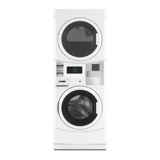
- Page 1 W10376697 ServiCe Manual Maytag Commercial Stacked Washer/Dryer MODELS: MLE20PDAYW0 MLE20PRAYW0 MLG20PDAWW0 MLG20PRAWW0 MLE20PDAZW0 MLE20PRAZW0 TeCHniCal eDuCaTiOn...
- Page 2 FOrWarD This Service Manual, (Part No. W10376697), provides the Commercial Laundry Service Professional with information on the installation, operation, and service of the Maytag Commercial Stacked Washer/Dryer. For specific information on the model being serviced, refer to the “Installation Instructions,” or “Tech Sheet” provided with the washer/dryer.
-
Page 3: Table Of Contents
TaBle OF COnTenTS Page View entire service video ....................viii Links to documents ......................viii General ..........................1-1 Model number designations ....................1-2 Serial number designations ....................1-2 Model & serial number label and tech sheet location ............1-3 Stacked washer/dryer specifications ................1-4 Warranty ........................... - Page 4 TaBle OF COnTenTS - COnTinueD Page COMPOnenT aCCeSS ......................4-1 Remove chemical dispenser drawer and parts ..............4-1 Remove control panel ....................... 4-3 Remove control board ...................... 4-4 Remove user interface display lens .................. 4-5 Install card reader ......................4-5 Remove payment system facia ..................
- Page 5 TaBle OF COnTenTS - COnTinueD Page Remove tub and spin basket assembly ................4-47 Replace washer baffle ...................... 4-50 Washer side panels and base ................... 4-51 Remove dryer console cover .................... 4-52 Remove dryer control board (CCU) .................. 4-53 Dryer CCU connections ....................4-54 Remove dryer door and hinge assembly ................
- Page 6 TaBle OF COnTenTS - COnTinueD Page Remove heater coil ......................4-87 COMPOnenT TeSTinG ......................5-1 Inlet valve solenoids ......................5-1 Pressure switch ........................ 5-2 RFI line filter ........................5-3 Door lock assembly ......................5-4 Drain pump motor ......................5-5 Temperature sensor ......................5-6 Drive motor ........................
- Page 7 TaBle OF COnTenTS - COnTinueD Page Water valve locations ......................6-15 Washer CCU wire harness connector table ..............6-15 Manually unlocking the door latch ..................6-15 Manually unlatching tripped door latch ................6-15 Washer care ........................6-16 Electronic assemblies removal or replacement ..............6-16 Washer clean-out cycle procedure ...................
-
Page 8: View Entire Service Video
inTeraCTive ServiCe Manual inSTruCTiOnS Click the mouse on any topic in the table of contents to go directly to that section. Click the mouse on any link that says (See page ?-?) to go directly to the page referenced. Click the mouse on any button in the links section to open the attached document. This symbol means a video clip is available. -
Page 9: General
General STaCkeD WaSHer / Dryer SaFeTy iMPORTANT Electrostatic Discharge (ESD) Sensitive Electronics ESD problems are present everywhere. ESD may damage or weaken the electronic control assembly. The new control assembly may appear to work well after repair is finished, but failure may occur at a later date due to ESD stress. -
Page 10: Model Number Designations
MODeL nuMBer DeSiGnaTiOnS MODel nuMBer DeSiGnaTiOnS MODeL nuMBer BranD Maytag DriVe TYPe Horizontal Axis Washer Non-Pedestal Horizontal Axis Washer w/Pedestal AH Automatic Horizontal Axis Washer LG Commercial Stacked Washer/Dryer PrODuCT 22 Commercial HE Front Load Washer Ends in 2011 30 Commercial HE Front Load Washer Starts in 2011... -
Page 11: Model & Serial Number Label And Tech Sheet Location
MODel & Serial nuMBer laBel anD TeCH SHeeT lOCaTiOn Location of Model & Serial Number Label Location of Tech Sheet, Parts List, Wiring Diagram & Service Key... -
Page 12: Stacked Washer/Dryer Specifications
STACKED W/D SPeCiFiCaTiOnS STaCkeD WaSHer/Dryer SPeCiFiCaTiOnS MLE/G20PRAYW0 MLE/G20PDAY W0 Model Number MLE20PDA MLE20PRA Model Description Front Load HE W asher with HE Dryer White / Black Accents Color Stainless Steel Trim Capacity Washer/Dryer 3.2 ft / 6.7 ft 6 Cycles Whites, Colors, Brights, Perm Press, Delicates &... -
Page 13: Warranty
For the first five years from the date of purchase, when this commercial appliance is installed, maintained and operated according to the instructions attached to or furnished with the product, Maytag brand of Whirlpool Corporation (thereafter “Maytag”) will pay for factory specified parts or original equipment manufacturer parts to correct defects in materials or workmanship. - Page 14 ---- nOTeS ----...
-
Page 15: Installation Requirements
inSTallaTiOn reQuireMenTS For complete installation instructions Parts supplied: See Links to documents page. Tools and parts Gather the required tools and parts before starting installation. The parts supplied are in the washer spin basket. Tools needed for connecting water inlet hoses: A. -
Page 16: Alternate Parts
If interested in purchasing any of the items accessories. For more high-quality items or to listed here, call toll-free order, call 1-800-901-2042, 1-800 NO BELTS (1-800-662-3587). or visit us at www.maytag.com/accessories. In Canada call: 1-800-807-6777 or visit us at www.whirlpoolparts.ca. Have Need to Buy... -
Page 17: Dimensions
DiMenSiOnS DIMENSIONS/CLEARANCES Dimensions Front View Side View Back View 27" 51" (686 mm) (1295 mm) 74" 74" (1880 mm) (1880 mm) 29.5 " 1" 1" (751 mm) (25 mm) (25 mm) ClearanCeS Clearances Side Clearances Back/Top Clearances 0" 0" (0 mm) (0 mm) -
Page 18: Stacked Washer/Gas Dryer Location Requirements
STaCkeD WaSHer/GaS Dryer lOCaTiOn reQuireMenTS You will need: WARNING A water heater set to deliver 120°F (49°C) water to the washer. A grounded electrical outlet located within 6 ft. (1.8 m) of where the power cord is attached to the back of the washer. See “Electrical Requirements.”... - Page 19 Stacked Washer/Gas Dryer installation recessed area and Closet installation Clearances instructions The location must be large enough to allow This washer/dryer may be installed in a the washer and dryer doors to be fully recessed area or closet. For recessed area opened.
-
Page 20: Stacked Washer/Gas Dryer Electrical Requirements
STaCkeD WaSHer/GaS Dryer eleCTriCal reQuireMenTS Do not ground to a gas pipe. Do not have a fuse in the neutral or ground circuit. A 120 volt, 60 Hz, AC only, 15- or 20- amp, fused electrical circuit is required. A time-delay fuse or circuit breaker is also recommended. - Page 21 Stacked Washer/Gas Dryer Grounding...
-
Page 22: Stacked Washer/Gas Dryer Gas Supply
STaCkeD WaSHer/GaS Dryer GaS SuPPly The design of this washer/dryer has been WARNING certified by CSA International for use at altitudes up to 10,000 feet (3048 m) above sea level at the B.T.U. rating indicated on the model/serial plate. Burner input adjustments are not required when the washer/dryer is operated up to this elevation. -
Page 23: Stacked Washer/Electric Dryer Location Requirements
STaCkeD WaSHer/eleCTriC Dryer lOCaTiOn reQuireMenTS Hot and cold water faucets located within WARNING 4 ft. (1.2 m) of the hot and cold water fill valves, and water pressure of 20–100 psi (137.9–689.6 kPa). A level floor with a maximum slope of 1” (25 mm) under entire washer/dryer. -
Page 24: Stacked Washer/Electric Dryer Installation Clearances
STaCkeD WaSHer/eleCTriC Dryer inSTallaTiOn ClearanCeS The location must be large enough to allow the washer and dryer doors to be fully opened. 48 in . Additional spacing should be considered for (310 cm 3" ease of installation and servicing. The doors (76 mm) open more than 180°. -
Page 25: Stacked Washer/Electric Dryer Electrical Requirements
STaCkeD WaSHer/eleCTriC Dryer eleCTriCal reQuireMenTS Washer electrical requirements Stacked Washer/electric Dryer Grounding Electrical Shock Hazard Plug into a grounded 3 prong outlet. Do not remove ground prong. Do not use an adapter. Do not use an extension cord. Failure to follow these instructions can result in death, fire, or electrical shock. - Page 26 Dryer electrical requirements electrical Connection It is your responsibility: To properly install the dryer, you must determine the type of electrical connection To contact a qualified electrical installer. you will be using and follow the instructions provided for it here. To be sure that the electrical connection This dryer is manufactured ready to is adequate and in conformance with the...
- Page 27 electric Dryer Power Supply Cord If your outlet looks like this: Then choose a 4-wire power WARNING supply cord with ring or spade terminals and UL listed strain relief. The 4-wire power supply cord, at least 4 ft. (1.22 m) 4-wire long, must have four 10-gauge receptacle...
-
Page 28: Dryer Venting Requirements
Dryer venTinG reQuireMenTS Dryer Direct Wire WARNING WARNING Fire Hazard Fire Hazard Use a heavy metal vent. Use 10 gauge copper wire. Do not use plastic vent. Use a UL listed strain relief. Do not use metal foil vent. Disconnect power before making Failure to follow these instructions electrical connections. - Page 29 Flexible metal vent: (Acceptable only if improper venting Can Cause Moisture and accessible to clean) lint To Collect indoors, Which May result Must be fully extended and supported in final dryer location. Moisture damage to woodwork, furniture, paint, wallpaper, carpets, etc. Remove excess to avoid sagging and kinking that may result in reduced airflow Housecleaning problems and health...
- Page 30 vent System length Connect vent Maximum Vent Length/Vent Connection If connecting to existing vent, make sure the vent is clean. Maximum length of vent system depends upon the type of vent used, number of elbows, Using a 4” (102 mm) clamp, connect vent to exhaust outlet in dryer.
- Page 31 if an exhaust Hood Cannot Be used Multiple Dryer venting The outside end of main vent should have a A main vent can be used for venting a group sweep elbow directed downward. of dryers. The main vent should be sized to remove 200 CFM of air per dryer.
-
Page 32: Dryer Gas Supply Requirements
Dryer GaS SuPPly reQuireMenTS Type Of Gas Gas Supply Pressure Testing This dryer is equipped for use with natural A 1/8” (3 mm) NPT minimum plugged tapping, gas. It is design-certified by CSA International accessible for gauge testing, must be installed for LP (propane and butane) gases with immediately downstream of the installed appropriate conversion. - Page 33 Flexible Metal appliance Connector It is recommended that a new flexible stainless steel gas line, design-certified by CSA International, be used for connecting the dryer to the gas supply line. (The gas pipe which extends through the lower rear of the dryer is provided with 3⁄8”...
-
Page 34: Gas Pipe Chart (Natural Gas)
GaS PiPe CHarT (naTural GaS) EXAMPLE: The chart shows the maximum capacity in terms of cubic feet of gas per hour, for various The dryer has a rating of 30,000 BTU. If the sizes of pipe at lengths of from 10 feet to 200 average BTU rating of natural gas is 1000, feet. -
Page 35: Washer Drain System
WaSHer Drain SySTeM laundry Tub Drain System The washer can be installed using the standpipe drain system (floor or wall), the Laundry tub needs a minimum 20 gal. (76 L) laundry tub drain system, or the floor drain capacity. The top of the laundry tub must be system. -
Page 36: Stacked Washer/Dryer Maintenance Instructions
STaCkeD WaSHer/Dryer MainTenanCe inSTruCTiOnS Washer Maintenance instructions: Cleaning The Door Seal/Bellow This washer has a special cycle that uses higher water volumes in combination with Open the washer door and remove any liquid chlorine bleach to thoroughly clean the clothing or items from the washer. inside of the washer. - Page 37 To exit out of the service mode and activate Washer the clean wash cycle, push the BRIGHTS button, then turn the key always Do The Following To Maintain Washer Freshness: nOTe: The door will lock, the basket will rotate 1/2 turn, then the door will unlock and Use only “HE”...
- Page 38 Water inlet Hoses Dryer Replace the inlet hoses after 5 years of use Maintenance instructions: to reduce the risk of hose failure. Periodically inspect and replace inlet hoses if bulges, Clean lint screen before and after each cycle. kinks, cuts, wear, or leaks are found. Removing accumulated lint: When replacing the inlet hoses, record the From inside the dryer cabinet:...
-
Page 39: Remove Shipping Bolts
reMOve SHiPPinG BOlTS reinSTall SHiPPinG BOlTS excessive Weight Hazard use two or more people to move and install stacked washer/dryer. Electrical Shock Hazard Failure to do so can result in back or Disconnect power before servicing. other injury. Replace all parts and panels before operating. - Page 40 ---- nOTeS ---- 2-26...
-
Page 41: Basic Operation
BaSiC OPeraTiOn eleCTrOniC COnTrOl SeTuP inSTruCTiOnS Dryer Display WHITES COLORS BRIGHTS PERM. DELICATES QUICK PRESS AND KNITS CYCLE WASHER DRYER WHITES PERM. & COLORS PRESS DELICATES Washer Display Dryer control fabric Washer control fabric setting buttons Display setting buttons nOTe: After the washer/dryer has been Door must be closed on the desired washer/ dryer before cycle selection is made. -
Page 42: General User Information
General uSer inFOrMaTiOn Scrolling “OuT OF OrDer” Followed By Diagnostic Code Showing in Display Electrical Shock Hazard This condition indicates the washer or dryer is Disconnect power before servicing. inoperative. Diagnostic codes being displayed Replace all parts and panels before on the upper portion of the display pertain operating. - Page 43 Warm Start (after power failure) Fixed Cycle With Top Off Pricing A few seconds after power is restored, if a A dryer set to offer “Top Off” capability will cycle was in progress at the time of the power allow time to be added to an existing dry failure, “RESELECT CYCLE”...
-
Page 44: Control Set-Up Procedure
COnTrOl SeT-uP uSinG THe BuTTOnS TO PrOCeDure PrOGraM THe COnTrOlS iMPOrTanT: Read all instructions before The lower-left (PERM. PRESS) button is used to adjust the values associated with operating. washer set-up codes and the upper-left (WHITES & COLORS) button is for the PD/PR Models: Insert service switch key dryer. -
Page 45: Start Operating Set-Up
STarT OPeraTinG SeT-uP SeT-uP CODeS Washer/dryers are preset at the factory and CODE EXPLANATION do not require any programming. However, 6 07 REGULAR CYCLE PRICE (WASHER) to change the settings, follow the “Set-Up 6 07 Represents the number of quarters (coin 1) needed to start the washer; Codes”... - Page 46 CODE EXPLANATION CODE EXPLANATION 7 05 OPTIONS TO USE IF SPECIAL PRICING IS SELECTED: REGULAR DRY TIME (DRYER) 7 05 3.07 SPECIAL CYCLE PRICE (WASHER) PD MODELS: Represents the number of minutes per quarter (coin 1). Factory default of 5 minutes per coin. Example: 6 quarters 3.07 Represents the number of quarters (coin 1) to start the washer;...
- Page 47 CODE EXPLANATION CODE EXPLANATION F.00 OPTIONS TO USE IF SPECIAL PRICING IS SELECTED (cont.): ENHANCED PRICING OPTION (WASHER) 9.10 F.00 SPECIAL PRICE DAY Not Selected ‘00’. 9.10 F.CP This represents the day of the week and whether special pricing Cycle-Based pricing enabled. This option allows configuration is selected for that day.
- Page 48 If cycle counter (9 0C) is selected, the CODE EXPLANATION n.CE following is true: CLEAR ESCROW OPTION When selected, money held in escrow for 30 minutes without 1 00 Cycles in Hundreds 1 02 = 200 further escrow or cycle activity will be cleared. n.00 Not selected ‘00’.
-
Page 49: Theory Of Operation
THeOry OF OPeraTiOn The idea behind the development of the Dryers have 3 fabric care settings and there Stacked Washer/Dryer was to have a product is no cycle available for drying without heat. with a small enough footprint that could deliver All dryers are factory preset to allow for 2 the same washing and drying capability as minutes of cool down at the end of a cycle. -
Page 50: Air Intake And Exhaust
air inTake anD exHauST air inTake anD exHauST Room temperature air (white arrows) enters The moistened heated air is drawn down Room temperature air (white arrows) enters The moistened heated air is drawn down the lower portion of the dryer through a gap through the lint filter, through the blower and the lower portion of the dryer through a gap through the lint filter, through the blower and... -
Page 51: Typical Cycle Of Operation
TyPiCal CyCle OF OPeraTiOn When WHITES AND COLORS is selected, 1. Thermal Fuse the high heat cycle is activated. The high temp 2. Exhaust Thermistor cycle uses the circuit that involves the 155°F 3. High temp cutout setting of the exhaust thermistor. 4. - Page 52 The belt switch is in series with the motor and has one of its leads connect directly to a terminal on the motor thermal overload. If either the belt switch or the motor thermal overload opens the circuit, it will stop the motor, which In turn will cause the motor centrifugal switch to open and change the positions of the motor switch, opening motor...
-
Page 53: Understanding The Gas Valve And Ignition System
unDerSTanDinG THe GaS valve anD iGniTiOn SySTeM The sensor, ignitor and gas valve are A significant voltage drop develops across interrelated and function as the ignition and the secondary coil, which renders both the heat source for gas dryers. At the start of the booster coil and the ignitor ineffective due to cycle the radiant sensor contacts are closed, their low resistance and the reduced voltage... -
Page 54: Cleaning The Dryer Location
iMPOrTanT: WARNING • Do not run the dryer with the lint screen loose, damaged, blocked, or missing. Doing so can cause overheating and damage to both the dryer and fabrics. • If lint falls off the screen into the dryer during removal, check the exhaust hood and remove the lint. -
Page 55: Cleaning The Dryer Interior
CleaninG THe Dryer inTeriOr To clean dryer drum: Unplug dryer or disconnect power. Make a paste with powdered laundry detergent and very warm water. Close shutoff valve in gas supply line. Apply paste to a soft cloth, or, apply a liquid Clean lint screen (See page 3-14). - Page 56 ---- nOTeS ---- 3-16...
-
Page 57: Component Access
COMPOnenT aCCeSS reMOve CHeMiCal DiSPenSer DraWer anD ParTS Pull the chemical dispenser drawer out as To remove the detergent flapper, place a far as it will go. flat blade screwdriver in the slot between the hinges at the top of the flapper and twist both ways to release the flapper. - Page 58 There is a bottom cover under the bleach To remove the front decorative plate of and fabric dispenser cups. This cover the chemical dispenser remove four T-20 should be removed and the siphon holes security screws. cleaned to maintain good elimination of chemicals during the cycle.
-
Page 59: Remove Control Panel
reMOve COnTrOl Panel Hook clip on the bottom edge of the service switch bracket into metal hoop to hold control panel open in the service position. Clip and Metal Hoop Electrical Shock Hazard Disconnect power before servicing. Replace all parts and panels before operating. -
Page 60: Remove Control Board
reMOve COnTrOl BOarD The small plastic cover on the back of the control board assembly holds the separate sub control board. Release two tabs and open the small cover to access this sub control board. Sub Control Electrical Shock Hazard Board Disconnect power before servicing. -
Page 61: Remove User Interface Display Lens
reMOve uSer inTerFaCe inSTall CarD reaDer DiSPlay lenS Electrical Shock Hazard Electrical Shock Hazard Disconnect power before servicing. Disconnect power before servicing. Replace all parts and panels before Replace all parts and panels before operating. operating. Failure to do so can result in death or Failure to do so can result in death or electrical shock. -
Page 62: Remove Payment System Facia
reMOve PayMenT SySTeM reMOve COin DrOP FaCia Electrical Shock Hazard Electrical Shock Hazard Disconnect power before servicing. Disconnect power before servicing. Replace all parts and panels before Replace all parts and panels before operating. operating. Failure to do so can result in death or Failure to do so can result in death or electrical shock. -
Page 63: Remove Coin Vault And Coin Vault Switch
reMOve COin vaulT anD COin vaulT SWiTCH Release the coin vault switch wires from the clip on the control panel bracket and slide the coin vault out of its support bracket. Remove two wire connectors from the back of the coin vault switch. Electrical Shock Hazard Control Panel 2 Coin Vault... -
Page 64: Remove Service Switch Assembly
reMOve ServiCe SWiTCH aSSeMBly Remove the lock from the front of the control panel cover. TeCH TiP: When reassembling the service switch assembly, place metal switch bracket against the control panel, and then the plastic bracket on top of the metal bracket. Electrical Shock Hazard Disconnect power before servicing. -
Page 65: Remove Keypad Assembly
reMOve keyPaD aSSeMBly Squeeze the securing clips that hold the keypad assembly inside the control panel cover. (See first photo in left column). Remove the keypad assembly from the front of the control panel cover. Electrical Shock Hazard Disconnect power before servicing. Replace all parts and panels before operating. -
Page 66: Remove Control Panel Bracket
reMOve COnTrOl Panel BraCkeT Push the wires through the hole of the bracket and remove the control panel bracket. The chemical dispenser adapter has clips on the back side of the control panel bracket that can be released once the bracket is Electrical Shock Hazard removed. -
Page 67: Remove Dryer From Stack
reMOve Dryer FrOM STaCk excessive Weight Hazard use two or more people to move and install stacked washer/dryer. Electrical Shock Hazard Failure to do so can result in back or Disconnect power before servicing. other injury. Replace all parts and panels before operating. -
Page 68: Remove Water Inlet Valves
reMOve WaTer inleT valveS Locking Tab Electrical Shock Hazard Disconnect power before servicing. Replace all parts and panels before operating. Failure to do so can result in death or electrical shock. Inlet Hoses Unplug washer or disconnect power. & Clamps Turn off the water supply to the washer. -
Page 69: Remove Water Inlet Valves From Back Without Removing Dryer
reMOve WaTer inleT valveS FrOM BaCk WiTHOuT reMOvinG Dryer Lower the valve to gain access to the hose clamps. Loosen the clamp and disconnect the hose from each water inlet valve to be removed. Lift the locking tab and disconnect the Rast connector to the water inlet valve Electrical Shock Hazard being removed. -
Page 70: Remove Chemical Dispenser Assembly
reMOve CHeMiCal DiSPenSer aSSeMBly Slide the chemical dispenser toward the rear of the washer to release the tab that secures it to the left side panel. Electrical Shock Hazard Keyhole Disconnect power before servicing. Slot Replace all parts and panels before operating. - Page 71 reaSSeMBly nOTe: When reconnecting Upper Cold Lower Cold Hot Water the main water inlet tube, align the arrow Valve 2 Valve 3 Valve 1 on the tube with the line on the chemical dispenser. Align the arrow on the flanged end of the tube with the arrow on the outer tub at approximately the 1:00 position.
-
Page 72: Remove Pressure Switch
reMOve PreSSure SWiTCH Rotate the pressure switch 90 degrees and pull the rectangular tab out of the slot in the top of the washer side panel. Pressure Electrical Shock Hazard Switch Disconnect power before servicing. Replace all parts and panels before operating. -
Page 73: Remove Rfi Line Filter
reMOve rFi line FilTer Slide the RFI line filter toward the water inlet valves to release the tabs in the slots. Power goes into the RFI line filter through the L1 and Neutral wire connectors. Power goes out through two pink wires to the CCU and the UIC transformer. -
Page 74: Remove Drain Hose And Fitting
reMOve Drain HOSe anD FiTTinG There is some foam insulation, on the drain hose inside the washer, to avoid damage from wear due to movement against the side panel of the washer. There is a clip that holds the drain hose at the back corner of the washer. -
Page 75: Remove Washer Power Cord (Mle Model Only)
reMOve WaSHer POWer COrD (Mle MODel Only) Remove the 1/4” hex head screw that secures the power supply cord strain relief to the rear panel of the washer. 1/4” Hex Head Screw Electrical Shock Hazard Disconnect power before servicing. Replace all parts and panels before operating. -
Page 76: Remove Door Lock / Switch Assembly
reMOve DOOr lOCk / SWiTCH aSSeMBly Use a small flat blade screwdriver in the loop at one end of the spring, and pull to expand the spring. Remove the retaining wire from the groove securing the bellow to the washer front panel. Electrical Shock Hazard Disconnect power before servicing. - Page 77 Reach in behind the front panel and pull the TeCH TiP: If the latch has been tripped, door lock assembly out. with the door open, by something being poked into the latch, it must be unlatched before the door will be able to be closed again.
-
Page 78: Remove Door Hook
reMOve DOOr HOOk reMOve DOOr anD HinGe aSSeMBly Open the washer door. Open the washer door. Remove two T-20 screws that secure the Remove two 1/4” hex head screws that hook to the door. secure the hinge to the front panel. Two 1/4”... -
Page 79: Washer Door Parts And Disassembly
WaSHer DOOr ParTS anD DiSaSSeMBly The door contains the outer lens, the outer Finish removing the outer door trim by hand. trim, the door handle, the inner trim, the glass bowl, the hinge and the door hook. The door handle can now be removed from the slots that are used to locate it on the nOTe: To avoid damage, lay a towel, or outer trim. - Page 80 To remove the door hinge, remove three Support the inner door trim to avoid having T-20 machine screws that secure the hinge it drop when removing the bowl brackets. to the inner door panel. The hinge is also used to hold part of the inner door panel and must be removed to replace the bowl.
-
Page 81: Remove Stacked Washer/Dryer Base
reMOve STaCkeD WaSHer/Dryer BaSe When reassembling the bowl and inner Disconnect all connections to the back of door trim, position the notch on the rim of the washer and/or the stacked washer/dryer. the bowl, at the bottom of the door, aligned with the 2 notches on the inner door panel. -
Page 82: Remove Washer Lower Service Panel
reMOve WaSHer lOWer ServiCe Panel Components located behind the washer lower service panel are: Drain pump Central control unit Motor control unit Electrical Shock Hazard Disconnect power before servicing. Ground switch Replace all parts and panels before Air gap dampers operating. -
Page 83: Remove Drain Pump
reMOve Drain PuMP Unscrew the pump filter and pull it out of the pump. If necessary, use a pair of pliers to loosen it. Electrical Shock Hazard Disconnect power before servicing. Replace all parts and panels before operating. Failure to do so can result in death or electrical shock. - Page 84 Disconnect the tub to pump hose by Lift clip on the front of the pump and slide squeezing the ears of the clamp and pulling wires down to release them from the clip. the hose off. (See page 4-27, last photo). Tub To Pump Hose Pump to Drain Hose Use a flat blade screwdriver to lift the right...
-
Page 85: Remove Drain Pump Motor
reMOve Drain PuMP MOTOr There may be a locking tab that is located near the top of the pump. Use a flat blade screwdriver to press the tab in toward the motor while twisting the motor off the pump. Electrical Shock Hazard Disconnect power before servicing. -
Page 86: Remove Tub To Pump Hose
reMOve TuB TO PuMP HOSe Remove the hose clamp from the pump and remove the hose. Remove the pressure switch hose from the air trap which is connected to the tub to pump hose with a wire tie. Electrical Shock Hazard nOTe: When removing only the air hose Disconnect power before servicing. -
Page 87: Remove Ground Switch
reMOve GrOunD SWiTCH When reinstalling the tub to pump hose, align the air hose fitting with the opening at the right side of the tub opening flange. There is also an alignment arrow on the pump that should be aligned with the notch on the hose. - Page 88 Use a flat blade screwdriver to press in on Push out on the 2 tabs of the switch holder, the 2 locking tabs in the bottom slots to rotate the switch in the direction of the release the switch. arrow, and remove the switch from the holder.
-
Page 89: Remove Washer Central Control Unit (Ccu)
reMOve WaSHer CenTral COnTrOl uniT (CCu) Use a small flat blade screwdriver to lift the locking tab that secures CCU to the washer. Locking Tab Electrical Shock Hazard Disconnect power before servicing. Replace all parts and panels before operating. Failure to do so can result in death or electrical shock. -
Page 90: Washer Ccu Connections
WaSHer CCu COnneCTiOnS Ensure that connectors are firmly seated onto the circuit board edge, and that the DS2 - Door Switch locks are properly engaged. 2 BU Wires Blue Stripe Pr6 - Pressure Switch 6 BU Wires user interface Seriel Port TH2 - Temp Sensor MCu interface 2 BK Wires... -
Page 91: Remove Motor Control Unit (Mcu)
reMOve MOTOr COnTrOl uniT (MCu) Cut the wire ties on the side of the MCU. Make sure not to cut the plastic base clip the wire tie secures to. Remove the base clips and install them on replacement MCU. Use a flat blade screwdriver to lift the Electrical Shock Hazard locking tab that secures the MCU to the base of the washer. -
Page 92: Remove Washer Rear Panel
reMOve WaSHer rear Panel Pull the bottom edge out and slide the panel down from behind the lip at the top edge to remove the panel. Components located behind the rear panel of the washer are: Electrical Shock Hazard Disconnect power before servicing. Drive belt Replace all parts and panels before Basket pulley... -
Page 93: Remove Washer Drive Belt
reMOve WaSHer Drive BelT Electrical Shock Hazard Disconnect power before servicing. Replace all parts and panels before operating. Failure to do so can result in death or electrical shock. Unplug washer or disconnect power. Turn off the water supply to the washer. The drive belt is a ribbed, fiber reinforced belt. -
Page 94: Remove Basket Pulley
reMOve BaSkeT Pulley Block the pulley to the rear of the tub to keep the spin basket from moving. Remove the 15/16” nut securing the pulley to the spin basket. Electrical Shock Hazard Disconnect power before servicing. Replace all parts and panels before operating. -
Page 95: Remove Vent Tube
reMOve venT TuBe To remove the vent tube from the washer, reach inside from the back of the washer and lift the vent tube to release 2 tabs from slots in the top back brace. Electrical Shock Hazard Disconnect power before servicing. Replace all parts and panels before operating. -
Page 96: Remove Temperature Sensor
reMOve TeMPeraTure SenSOr Remove and replace the grommet only if necessary. When installing a grommet, the flanges of the grommet must seal inside and outside of the hole in the outer tub. Electrical Shock Hazard Disconnect power before servicing. It is easier to reinstall the grommet once it is Replace all parts and panels before separated from the sensor. -
Page 97: Remove Motor
reMOve MOTOr Remove the 1/2“ bolt securing the motor to the tub. 1/2” Motor Bolt Electrical Shock Hazard Disconnect power before servicing. Replace all parts and panels before operating. Failure to do so can result in death or electrical shock. Rotate the motor down and slide the Unplug washer or disconnect power. -
Page 98: Remove Air Gap Damper
reMOve air GaP DaMPer The damper is attached to the base in the same way, with 2 locking tabs. Electrical Shock Hazard Disconnect power before servicing. Replace all parts and panels before operating. Failure to do so can result in death or 1/4 Turn electrical shock. -
Page 99: Remove Washer Front Panel
reMOve WaSHer FrOnT Panel Remove two 1/4” hex head screws, that were hidden by the control panel cover, that secure the top of the front panel to the washer side panels. Electrical Shock Hazard Disconnect power before servicing. Replace all parts and panels before operating. -
Page 100: Remove Uic Transformer
reMOve uiC reMOve THe BellOW TranSFOrMer Electrical Shock Hazard Electrical Shock Hazard Disconnect power before servicing. Disconnect power before servicing. Replace all parts and panels before Replace all parts and panels before operating. operating. Failure to do so can result in death or Failure to do so can result in death or electrical shock. - Page 101 Remove the bellow retaining clamp from nOTe: When reinstalling the bellow, it is around the bellow. important to position the weep holes at the bottom center of the cabinet opening. Removal of the front weights will make it much easier to reinstall the bellow. If there is a complaint that water rolls out the door when the clothes are removed from the washer, adjust the front leveling legs slightly...
-
Page 102: Remove Washer Front Support Bracket
reMOve WaSHer FrOnT SuPPOrT BraCkeT Remove three T-20 screws from the washer front support bracket that secure the top and front of the chemical dispenser. Three T-20 Screws Electrical Shock Hazard Disconnect power before servicing. Replace all parts and panels before operating. -
Page 103: Remove Tub And Spin Basket Assembly
reMOve TuB anD SPin BaSkeT aSSeMBly Disconnect the ground wire to the hub at the spade connection about 12 inches from the hub. Follow the ground wire from the hub to the connector to locate the disconnecting point. Electrical Shock Hazard Disconnect power before servicing. - Page 104 Lift tub straight up to separate the air gap Remove three 1/2” bolts that secure the dampers and move it forward out of cabinet. lower front weight to the outer tub, and remove the weight. nOTe: To avoid damage to components in the cabinet base or on the outer tub, do not Remove three 1/2”...
- Page 105 Mark any position on the outer tub that There is a gasket, that seals the tub halves does not have a clamp. together, in the channel around the edge of the rear outer tub. This gasket should be replaced after separating the outer tub. Remove the tub clamps by prying them off with a flat blade screwdriver.
-
Page 106: Replace Washer Baffle
rePlaCe WaSHer BaFFle Electrical Shock Hazard Disconnect power before servicing. Replace all parts and panels before operating. Failure to do so can result in death or electrical shock. Unplug washer or disconnect power. Turn off the water supply to the washer. Remove the tub and spin basket assembly (See page 4-47). -
Page 107: Washer Side Panels And Base
WaSHer SiDe PanelS anD BaSe Electrical Shock Hazard Disconnect power before servicing. Replace all parts and panels before operating. Failure to do so can result in death or electrical shock. The side panels of the washer are mechanically crimped to the base due to the weight of the washer/dryer and for structural integrity. -
Page 108: Remove Dryer Console Cover
reMOve Dryer COnSOle COver nOTe: The wires inside the console are just long enough to allow the cover to rotate up onto the top of the dryer. If the wires are too tight and the panel cannot lift onto the top of the dryer, disconnect the tight wires from the CCU to avoid damaging the connectors on the CCU. -
Page 109: Remove Dryer Control Board (Ccu)
reMOve Dryer COnTrOl BOarD (CCu) Press two locking tabs just enough to release one edge of the board. Locking Tabs Electrical Shock Hazard Disconnect power before servicing. Replace all parts and panels before operating. Failure to do so can result in death or electrical shock. -
Page 110: Dryer Ccu Connections
Dryer CCu COnneCTiOnS N.O. Heater Motor Yellow-Red Lt. Blue Black Black Relay 1 Relay Red-White Black-White Open White Green-Yellow Open Dryer Central Control Unit Connections Open (Elec.) Orange (Gas) Red-White 4-54... -
Page 111: Remove Dryer Door And Hinge Assembly
reMOve Dryer DOOr anD HinGe aSSeMBly The door hinge, on both the doors of the Grasp the door and pull the hook of the stack washer/dryer, swing completely open, hinge out of the slot in front panel, then lift 180 degrees. door hinge off the screw. -
Page 112: Reverse A Dryer Door
reverSe a Dryer DOOr Install the hinge screw-hole cover on the opposite side of the door opening. Align the two pins, on the back of the cover, with the two middle holes for the door hinge. Electrical Shock Hazard Disconnect power before servicing. Replace all parts and panels before operating. - Page 113 Remove four star head screws that secure Rotate the outer door 180 degrees. Place the hinge to the door. the inner door into the outer door with the hinge on the opposite side of the handle. Rotate the hinge 180 degrees and install Hinge it on the other side of the door with the four screws just removed.
-
Page 114: Remove Dryer Door Handle
reMOve Dryer DOOr reMOve Dryer inner HanDle DOOr lenS To remove door handle after the door halves Separate door halves (See page 4-56). are separated (See page 4-56), remove three star head screws. Remove door handle (See left column on this page). -
Page 115: Remove Dryer Drum Light Lens
reMOve Dryer DruM liGHT lenS nOTe: There is no light socket on a commercial dryer, nor is there capability of adding a light on commercial dryers. The lens is maintained as a safety device. Behind the light lens is a bracket with a mesh screen. -
Page 116: Remove Dryer Front Panel
reMOve Dryer FrOnT Panel Release the door switch wire from the clip on the lint filter housing. Squeeze the Christmas tree clip on the back side of the housing to release the wire harness clip with wire harness attached. Electrical Shock Hazard Wire Disconnect power before servicing. -
Page 117: Remove Dryer Lint Filter Housing
reMOve Dryer linT FilTer HOuSinG Electrical Shock Hazard Disconnect power before servicing. Replace all parts and panels before operating. Failure to do so can result in death or electrical shock. Remove the dryer front panel (See page 4-60). Remove four 1/4” hex head screws. If the two screws going into the blower housing are brass, and the others are not, they must be replaced in the same location they are... -
Page 118: Remove Dryer Front Bulkhead
reMOve Dryer FrOnT BulkHeaD Squeeze the Christmas tree clips, from the inside of the bulkhead, to release the wire from the front right side. Christmas Wire On Front Tree Clip Bulkhead Electrical Shock Hazard Disconnect power before servicing. Replace all parts and panels before operating. -
Page 119: Remove Dryer Outlet Grill
reMOve Dryer OuTleT Grill Lift outlet grill off front bulkhead. Separate the two halves of the outlet grill by pulling them apart. Electrical Shock Hazard Disconnect power before servicing. Replace all parts and panels before operating. Failure to do so can result in death or electrical shock. -
Page 120: Remove Dryer Front Support Rollers And Shafts
reMOve Dryer FrOnT SuPPOrT rOllerS anD SHaFTS nOTe: DO NOT lubricate this wheel or shaft. Lubrication attracts lint and dust which will cause premature wear of the support bearing. Clean shaft with fine steel wool to eliminate squeaks, or replace worn rollers. -
Page 121: Remove Dryer Top Panel
reMOve Dryer TOP Panel Lift the back edge of the top. Slide it back slightly to unhook the tab from the slot in the channel at the front edge. Top Panel Front Tab Electrical Shock Hazard Disconnect power before servicing. Replace all parts and panels before operating. -
Page 122: Remove Dryer Console Bracket
reMOve Dryer COnSOle BraCkeT Remove two 1/4” hex head screws that secure the console bracket to the edges of the right side panel. 1/4” Hex Head Screw Electrical Shock Hazard Disconnect power before servicing. Replace all parts and panels before operating. -
Page 123: Remove Dryer Belt
reMOve Dryer BelT TeCH TiP: The belt does not ride in the wide groove on the drum, commonly called the belly band. There is more clearance between the belt and the top of the dryer, therefore the belt does not need to ride in the lower part of the belly band. -
Page 124: Remove Dryer Drum
reMOve Dryer DruM Install dryer drum with the drum clip, plug or hole closer to the rear bulkhead of the dryer. This is opposite the orientation of the drum in the dryer that matches a top load washer. This orientation will allow for quieter operation because the drum supports roll in this direction without a thump, as they roll Electrical Shock Hazard... -
Page 125: Remove A Dryer Baffle
reMOve a Dryer BaFFle Open dryer door and hold baffle with one hand while removing the third screw. Electrical Shock Hazard Disconnect power before servicing. Replace all parts and panels before operating. Failure to do so can result in death or Baffle electrical shock. -
Page 126: Remove Dryer Thermistor
reMOve Dryer reMOve Dryer THerMal THerMiSTOr FuSe Electrical Shock Hazard Electrical Shock Hazard Disconnect power before servicing. Disconnect power before servicing. Replace all parts and panels before Replace all parts and panels before operating. operating. Failure to do so can result in death or Failure to do so can result in death or electrical shock. -
Page 127: Remove Dryer Blower Wheel
reMOve Dryer BlOWer WHeel To remove blower wheel when speed increaser belt is broken, slipping or missing, a thin 7/16” open end wrench WIll be needed to secure speed increaser shaft on its flat spot, in lieu of securing the motor pulley. -
Page 128: Remove Dryer Blower Housing
reMOve Dryer BlOWer HOuSinG Remove three 1/4” hex head screws from inside the blower housing that secure it to the motor bracket. Three 1/4” Hex Head Screws Electrical Shock Hazard Disconnect power before servicing. Replace all parts and panels before operating. -
Page 129: Remove Dryer Exhaust Duct
reMOve Dryer exHauST DuCT TeCH TiP: When reinstalling exhaust duct, or for new dryer installations, make sure the anti-vibration ring for the exhaust duct is installed in the hole in the back panel of dryer. This ring cannot be installed or removed with the exhaust duct in place. -
Page 130: Remove Dryer Motor And Speed Increaser
reMOve Dryer MOTOr anD SPeeD inCreaSer To remove the motor wire harness, lift the locking tab with a flat blade screwdriver and pull the plug off the motor connector. Wire Harness Electrical Shock Hazard Disconnect power before servicing. Replace all parts and panels before operating. - Page 131 To remove the speed increaser, remove the nOTe: The centrifugal switch is the brown belt from the speed increaser. disc that actuates the lever of the motor switch when the motor is at rest. Remove the two 5/16” hex head screws that secure the speed increaser to the front of the motor.
-
Page 132: Remove Dryer Motor Bracket
reMOve Dryer MOTOr BraCkeT TeCH TiP: To reduce excess vibration transferred from the motor bracket to the cabinet, place anti-vibration pads, if they are missing, under the motor bracket. Install two pads if possible, or if only one is available, then center it below the bracket. Electrical Shock Hazard Disconnect power before servicing. -
Page 133: Remove Dryer Belt Switch
reMOve Dryer BelT reMOve Dryer iDler SWiTCH Pulley Electrical Shock Hazard Electrical Shock Hazard Disconnect power before servicing. Disconnect power before servicing. Replace all parts and panels before Replace all parts and panels before operating. operating. Failure to do so can result in death or Failure to do so can result in death or electrical shock. -
Page 134: Remove Drum Rear Support Rollers
reMOve DruM rear reMOve rear SuPPOrT SuPPOrT rOllerS rOller SHaFTS Electrical Shock Hazard Electrical Shock Hazard Disconnect power before servicing. Disconnect power before servicing. Replace all parts and panels before Replace all parts and panels before operating. operating. Failure to do so can result in death or Failure to do so can result in death or electrical shock. -
Page 135: Remove Rear Panel
reMOve rear Panel Remove ten 1/4” hex head screws that secure the rear panel to the dryer. Electrical Shock Hazard Disconnect power before servicing. Replace all parts and panels before operating. Failure to do so can result in death or electrical shock. -
Page 136: Remove Dryer Side Panel (Left Side Shown)
reMOve Dryer SiDe Panel (leFT SiDe SHOWn) Support side panel and lift rear bulkhead and move it forward to release hook from the back edge of the side panel. Electrical Shock Hazard Disconnect power before servicing. Replace all parts and panels before operating. -
Page 137: Remove Rear Bulkhead
reMOve rear BulkHeaD reMOve HeaT PlenuM Electrical Shock Hazard Electrical Shock Hazard Disconnect power before servicing. Disconnect power before servicing. Replace all parts and panels before Replace all parts and panels before operating. operating. Failure to do so can result in death or Failure to do so can result in death or electrical shock. -
Page 138: Remove Flame Sensor
reMOve FlaMe SenSOr reMOve HiGH TeMP THerMOSTaT Electrical Shock Hazard Electrical Shock Hazard Disconnect power before servicing. Disconnect power before servicing. Replace all parts and panels before Replace all parts and panels before operating. operating. Failure to do so can result in death or Failure to do so can result in death or electrical shock. -
Page 139: Remove High Temp Cutout
reMOve HiGH TeMP reMOve iGniTOr CuTOuT Electrical Shock Hazard Electrical Shock Hazard Disconnect power before servicing. Disconnect power before servicing. Replace all parts and panels before Replace all parts and panels before operating. operating. Failure to do so can result in death or Failure to do so can result in death or electrical shock. -
Page 140: Remove Gas Valve Coils
reMOve GaS valve COilS reMOve GaS Burner aSSeMBly Electrical Shock Hazard Electrical Shock Hazard Disconnect power before servicing. Disconnect power before servicing. Replace all parts and panels before Replace all parts and panels before operating. operating. Failure to do so can result in death or Failure to do so can result in death or electrical shock. -
Page 141: Remove Gas Valve From Bracket
reMOve GaS valve FrOM BraCkeT Remove three 1/4” hex head screws from bottom of bracket. Electrical Shock Hazard Disconnect power before servicing. Replace all parts and panels before operating. Failure to do so can result in death or electrical shock. Three 1/4”... -
Page 142: Remove Electric Heating Element
reMOve eleCTriC HeaTinG eleMenT Lift bracket and heater assembly to remove the bottom edge of the assembly and press down to release the tab from inside the heat plenum at the back of the dryer. Electrical Shock Hazard Positioning Disconnect power before servicing. Replace all parts and panels before operating. -
Page 143: Remove Heater Coil
reMOve HeaTer COil nOTe: Heater element assemblies have a serviceable electric coil element. Since the element is serviceable: remove the heater coil from the housing using one pair of pliers to hold the housing and another pair of pliers to pull the heater coil up out of the housing. - Page 144 ---- nOTeS ---- 4-88...
-
Page 145: Component Testing
COMPOnenT TeSTinG Before testing any of the components, perform • Check all connections before replacing components, looking for broken or loose the following checks: wires, failed terminals, or wires not pressed • Control failure can be the result of corrosion into connectors far enough. -
Page 146: Pressure Switch
Electrical Shock Hazard Disconnect power before servicing. Replace all parts and panels before operating. Failure to do so can result in death or electrical shock. PreSSure SWiTCH See page 4-16 for the procedure for accessing the pressure switch. To check the pressure switch at the component terminals, perform the following steps. -
Page 147: Rfi Line Filter
Electrical Shock Hazard Disconnect power before servicing. Replace all parts and panels before operating. Failure to do so can result in death or electrical shock. rFi line FilTer To check the RFI line filter at the CCU, perform the following steps. Unplug washer or disconnect power. -
Page 148: Door Lock Assembly
Electrical Shock Hazard Disconnect power before servicing. Replace all parts and panels before operating. Failure to do so can result in death or electrical shock. DOOr lOCk aSSeMBly Disconnect the door switch connector (See page 4-34) from the CCU. Door Lock Solenoids To test the door switch, touch the ohmmeter test leads to pins 3 and 1 at DS2. -
Page 149: Drain Pump Motor
Electrical Shock Hazard Disconnect power before servicing. Replace all parts and panels before operating. Failure to do so can result in death or electrical shock. Drain PuMP MOTOr To check the drain pump at the CCU, perform the following steps. Unplug washer or disconnect power. -
Page 150: Temperature Sensor
Electrical Shock Hazard Disconnect power before servicing. Replace all parts and panels before operating. Failure to do so can result in death or electrical shock. TeMPeraTure SenSOr See page 4-40 for the procedure for accessing To check the temperature sensor at the CCU, the temperature sensor. -
Page 151: Drive Motor
Electrical Shock Hazard Disconnect power before servicing. Replace all parts and panels before operating. Failure to do so can result in death or electrical shock. Drive MOTOr GrOunD SWiTCH N.C. Actuator Button See page 4-31 for the procedure for accessing a ground switch. -
Page 152: User Interface Membrane Switch
Electrical Shock Hazard Disconnect power before servicing. Replace all parts and panels before operating. Failure to do so can result in death or electrical shock. uSer inTerFaCe MeMBrane SWiTCH See page 4-9 for the procedure for accessing 9 Button User Interface Membrane Switch the keypad assembly. -
Page 153: Coin Drop Acceptor
Electrical Shock Hazard Disconnect power before servicing. Replace all parts and panels before operating. Failure to do so can result in death or electrical shock. COin DrOP aCCePTOr The coin drop acceptor is used only on the The coin sensor is mounted to a bar located PD model washers. -
Page 154: Transformer
Electrical Shock Hazard Disconnect power before servicing. Replace all parts and panels before operating. Failure to do so can result in death or electrical shock. TranSFOrMer Unplug washer or disconnect power. Transformer Primary Winding Set the ohmmeter to the R X 1 scale. Connector Set digital ohmmeters to lowest scale. -
Page 155: Gas Valve Coils
Electrical Shock Hazard Disconnect power before servicing. Replace all parts and panels before operating. Failure to do so can result in death or electrical shock. GaS valve COilS The gas valve is actually a regulator and 2 valves in 1. Each valve is in series with the other. -
Page 156: Burner Ignitor
Burner Ignitor The pressure is then read on the manometer as the water column pushes downward. The water column (W.C.) for a Maytag dryer is 3.5” W.C. for Natural gas and 11” W.C. for LP gas. 5-12... - Page 157 Electrical Shock Hazard Disconnect power before servicing. Replace all parts and panels before operating. Failure to do so can result in death or electrical shock. How to use: When the gas is on, the amount of water column present is equal to the total amount Disconnect power supply to dryer.
-
Page 158: Flame Sensor
Electrical Shock Hazard Disconnect power before servicing. Replace all parts and panels before operating. Failure to do so can result in death or electrical shock. HiGH TeMP THerMOSTaT FlaMe SenSOr & HiGH TeMP CuTOuT (GaS DryerS Only) Unplug dryer or disconnect power. The high temp cutout is a non-resettable device. -
Page 159: Heating Element (Electric Dryers Only)
Electrical Shock Hazard Disconnect power before servicing. Replace all parts and panels before operating. Failure to do so can result in death or electrical shock. HeaTinG eleMenT (eleCTriC DryerS Only) Unplug dryer or disconnect power. Remove the electric heating element. (See page 4-86). -
Page 160: High Temp Cutout (Electric Dryers Only)
Electrical Shock Hazard Disconnect power before servicing. Replace all parts and panels before operating. Failure to do so can result in death or electrical shock. HiGH TeMP CuTOuT (eleCTriC DryerS Only) Access the Electric Heating Element High Temp (See page 4-86). Cutout The high temp cutout is a non resettable High Temp... -
Page 161: Centrifugal Switch
Electrical Shock Hazard Disconnect power before servicing. Replace all parts and panels before operating. Failure to do so can result in death or electrical shock. CenTriFuGal SWiTCH Unplug dryer or disconnect power. If no continuity is found when the disc is depressed, change the centrifugal switch. -
Page 162: Drive Motor
Electrical Shock Hazard Disconnect power before servicing. Replace all parts and panels before operating. Failure to do so can result in death or electrical shock. Drive MOTOr The motor features a leadless motor Set the ohmmeter to the R X 1 scale. connection, comprised of a quick connector Set digital ohmmeters to lowest scale. - Page 163 If the resistances at the motor are correct, check for a failed belt switch. Continuity test should show complete circuit (0 Ω) with belt installed completely. If the belt switch checks okay, perform same test for motor thermal overload. Motor Connector Belt Switch 5-19...
-
Page 164: Thermistor
Electrical Shock Hazard Disconnect power before servicing. Replace all parts and panels before operating. Failure to do so can result in death or electrical shock. THerMiSTOr Check the thermistor resistance value The table below gives the resistance values at any or all of the temperature levels in that should be observed for the various question, using the Dry Cycle, and the temperature settings. -
Page 165: Thermal Fuse
Electrical Shock Hazard Disconnect power before servicing. Replace all parts and panels before operating. Failure to do so can result in death or electrical shock. THerMal FuSe Unplug dryer or disconnect power. The thermal fuse is wired in series with the drive motor. -
Page 166: Transformer
Electrical Shock Hazard Disconnect power before servicing. Replace all parts and panels before operating. Failure to do so can result in death or electrical shock. TranSFOrMer Unplug dryer or disconnect power. Set the ohmmeter to the R X 1 scale. Set digital ohmmeters to lowest scale. -
Page 167: Diagnosis & Troubleshooting
1 second while in set-up code six, anytime washer operation, including pressure switch a diagnostic code is present, or while dAS behavior. displays if operating with Maytag Data Acquisition set-up. Washer Quick Spin Cycle – With the entire display flashing, this cycle is started by pressing the center middle (COLORS) button. -
Page 168: Failure Displays
Dryer DiaGnOSTiC CODeS Washer Quick Overview Test Cycle – With ACCU the entire display flashing, this cycle is TRAC DRYER ® started by pressing the lower middle INDICATION DISPLAY EXPLANATION (DELICATES AND KNITS) button. This COIN 1 ERROR cycle provides a quick verification that the Blocked coin 1 or coin drop UI control circuit failure cold and hot water valves, dispenser, and (coin recognition and customer display disabled while... -
Page 169: Washer Diagnostic Codes
WaSHer DiaGnOSTiC CODeS If the set-up mode is entered and one of ACCU the following washer errors has previously TRAC WASHER ® INDICATION DISPLAY EXPLANATION AND RECOMMENDED PROCEDURE occurred, the appropriate diagnostic code will NO WATER DETECTED ENTERING WASHER F 20 be in the display on the lower portion of the The first level of pressure switch is not tripped after screen. - Page 170 ACCU ACCU TRAC WASHER ® TRAC WASHER ® INDICATION DISPLAY EXPLANATION AND RECOMMENDED PROCEDURE INDICATION DISPLAY EXPLANATION AND RECOMMENDED PROCEDURE DOOR LOCK ERROR TACHOMETER ERROR d 1 7 F 22 d 1 2 F 2 5 Washer will make several attempts to lock the door, If the MCU is unable to properly detect motor speed, then customer will be asked to open door, clear the washer shuts down.
- Page 171 ACCU ACCU TRAC WASHER TRAC WASHER ® ® INDICATION DISPLAY EXPLANATION AND RECOMMENDED PROCEDURE INDICATION DISPLAY EXPLANATION AND RECOMMENDED PROCEDURE OVERFLOW CONDITIONS DOOR UNLOCK ERROR d 1 9 F 29 d 2 1 F 2 7 The overflow contact on the pressure switch is closed The door is unable to unlock after 6 tries.
- Page 172 ACCU ACCU TRAC WASHER TRAC WASHER ® ® INDICATION DISPLAY EXPLANATION AND RECOMMENDED PROCEDURE INDICATION DISPLAY EXPLANATION AND RECOMMENDED PROCEDURE UIC FAILURE PUMP DISCONNECTED F 73 d 1 4 F 33 Communication error within the User Interface Control. The electrical connection between the pump and the F 74 CCU is lost.
- Page 173 ACCU TRAC WASHER ® INDICATION DISPLAY EXPLANATION AND RECOMMENDED PROCEDURE COIN 2 ERROR d 1 3 d 1 3 The Coin 2 sensor is detected as blocked for 8 seconds. Possible Causes – Coin vault full of money. – Blocked or dirty sensor. Procedure 1.
-
Page 174: Washer Quick Overview Test
WaSHer QuiCk OvervieW TeST This cycle consists of 8 steps. In each step, press lower right (QUICK CYCLE) button. the washer will perform a Control Action The drain pump may be running in any of the as described in the table below. Once the last 3 steps, depending on the water level action is completed, the washer will move to the next step. -
Page 175: Washer Manual Overview Test
WaSHer Manual OvervieW TeST Before replacing any system components, perform this Manual Overview Test. This cycle consists of 7 steps. In each step, the washer will perform a Control Action as described in the table below. Once the action is completed, the washer will move to the next step. -
Page 176: Diagnostic Test Quick Guide
DiaGnOSTiC TeST QuiCk GuiDe The following table summarizes keypad function among the diagnostic sub-modes. Diagnostic Mode Keypad Function Table Function in Function in Function in Diag. Function in Diag. Function in Diag. Cycle Diag. Code Display Flashing Cycle Running Sub-Mode Cycle Running Sub-Mode Running Sub-Mode Button... -
Page 177: Washer Help Codes
WaSHer HelP CODeS Dryer HelP CODeS Help Codes Help Codes Help Help Code Code Description (Hex) Description Generation 2 debit card cycle polling message out of sequence Oversuds detected during cycle, and washer was not able to resolve Generation 2 debit card remaining balance message out of sequence an unbalance condition detected during the final spin related to the oversuds detection (via pressure sensor) earlier in the cycle. -
Page 178: Help Mode Submenu
Help mode is entered by pressing the lower left (PERM. PRESS) button while in special pricing option 2.XX (or while dAS displays if operating with Maytag Data Acquisition setup). In help mode, the software revision is displayed. This sub-menu consists of many steps. -
Page 179: Help Mode Symbols And Elements
HelP MODe SyMBOlS anD eleMenTS Along with the steps of the help mode, symbols and elements are mapped, at all times, to reflect the state of various inputs and outputs. Dryer (Upper) Washer (Lower) Display Symbol Description Display Symbol Description Dryer motor sensed on WASH Water sensed above wash level... -
Page 180: Washer Pump Motor Continuity Test
WaSHer PuMP MOTOr WaTer TeMPeraTure COnTinuiTy TeST SenSOr Unplug washer or disconnect power. Pins Result 1 to 2 Normal = Approx. 12.3 ohms Disconnect the wire harness from the Abnormal = Infinity water temperature sensor and measure the resistance of the sensor. Use the following table. -
Page 181: Water Valve Locations
WaTer valve lOCaTiOnS Manually unlOCkinG THe DOOr laTCH Water Valve Locations Unplug washer or disconnect power. Hot Inlet Cold Inlet Cold Inlet Valve #1 Valve #2 Valve #3 Remove the washer lower service panel Reach up along the inside of the front panel and locate the bottom of the door switch / lock assembly. -
Page 182: Washer Care
eleCTrOniC aSSeMBlieS WaSHer Care reMOval Or rePlaCeMenT Cleaning the door seal: iMPOrTanT: Electrostatic (static electricity) Open the washer door and remove any discharge may cause damage to electronic clothing or items from the washer. control assemblies. (See page 3-2) for details. Inspect the colored rubber seal between the nOTe: Be sure to perform the Diagnostic front panel and the spin basket for stains. -
Page 183: Washer Clean-Out Cycle Procedure
WaSHer Clean-OuT CyCle PrOCeDure This washer has a special cycle that uses The cycle will determine if clothing or other higher water volumes in combination with items are in the washer. liquid chlorine bleach and hot water to a) If no items are detected in the washer, it will proceed to step 7. -
Page 184: Washer Troubleshooting Guide
WaSHer TrOuBleSHOOTinG GuiDe PROBLEM POSSIBLE CAUSE / TEST nOTe: Possible Cause / Tests must be performed in the sequence shown for each problem. Blank display Possible Causes – UIC not powered or no power to the washer/dryer. – Wrong communication between CCU and UIC. Procedure for uiC not powered 1. -
Page 185: Dryer Troubleshooting Guide
PROBLEM POSSIBLE CAUSE / TEST Drum won’t rotate 1. Check for broken drive belt. 2. Check for drive motor failure error codes (F11, F25, F28). • Check the electrical connection and verify the function of the cable between the MCU and drive motor. 3. -
Page 186: Troubleshooting Tests
TrOuBleSHOOTinG TeSTS In a similar way, check which terminal of the plug is connected to the left-most contact on the terminal block and make a note of it. This will be L1 (black wire) in the wiring diagram. Power Cord Terminal Block Electrical Shock Hazard Plug... - Page 187 Check the cable connecting the CCU to UIC GaS Dryer is inserted all the way into the dryer CCU Unplug dryer or disconnect power. (control board) at P2 & onto UIC connector WC3. Remove the cover plate from the upper right corner of the back of the dryer.
- Page 188 In a similar way, check the continuity TeST #2 Motor Circuit Test between the L1 terminal of the plug and P9-2 (black wire) on the CCU control board. This test will check the wiring to the motor and (See page 4-54). the motor itself.
- Page 189 Check the belt switch (See page 4-77), and Check for the resistance values of the motor drive motor (See page 4-74). Remove the Main and Start winding coils as shown drum belt from the spring loaded idler pulley below. (See page 4-77). nOTe: Main and Start winding coils must be checked at the motor.
- Page 190 • If the resistance reading goes from infinity TeST #3 Heater Test to a few ohms as pulley arm closes the switch, belt switch is OK. If not, replace the This test is performed when either of the belt switch. following situations occur: •...
- Page 191 GaS Dryer: Dryer does not heat: eleCTriC Dryer: Unplug dryer or disconnect power. Unplug dryer or disconnect power. Remove the control panel bracket to access the thermal components (See page 4-10). Remove the control panel bracket to access the thermal components. (See page 4-10). Perform TEST #3b.
- Page 192 Begin with an empty dryer and clean lint If the exhaust temperature is not within specified limits, unplug dryer or disconnect screen. power. Plug in dryer or reconnect power. Check the resistance of the thermistor. Start a Drying cycle. nOTe: Thermistor resistance measurements must be made while dryer is disconnected from power.
- Page 193 TeST #3b Thermal Fuse Test TeST #3d Gas valve Test, Gas Dryer Only eleCTriC Dryer: The thermal fuse is Unplug dryer or disconnect power. wired in series with the dryer drive motor. Access the gas valve (See page 4-84). GaS Dryer: The thermal fuse is wired in series with the dryer gas valve.
-
Page 194: Unusual Sounds
unuSual SOunDS Test #4 Door Switch Test • Has the dryer had a period of non-use? If the dryer has not been used for a while, Activate Diagnostic Test Mode, and perform there may be a thumping sound during the a Door Switch Test. -
Page 195: Dryer Displaying Code Message
Dryer DiSPlayinG CODe MeSSaGe A scrolling “out of order” message in the display indicates failure mode. The code following the message is the best indicator of the problem. Check the diagnostic codes in the tech sheet (Document Links Page). 6-29... -
Page 196: Troubleshooting Dryer Results
TrOuBleSHOOTinG Dryer reSulTS Clothes are not drying satisfactorily, drying times too long, or load is too hot • is the lint screen clogged with lint? • is the dryer located in a closet? Lint screen should be cleaned before each Closet doors must have ventilation openings load. -
Page 197: Lint On Load
lint on load • is the lint screen clogged? Clean lint screen. Check for air movement. Stains on load or drum • Was dryer fabric softener properly used? Add dryer fabric softener sheets at the beginning of the cycle. Fabric softener sheets added to a partially dried load can stain garments. - Page 198 ---- nOTeS ---- 6-32...
-
Page 199: Wiring Diagrams
WirinG DiaGraMS u.S. eleCTriC TERMINAL CONSTRUCTION SPLICE BK - LINE L1 R - LINE L2 IN LINE CONNECTION 240 VOLTS W - NEUTRAL N 120 VOLTS EXHAUST THERMISTOR DOOR SWITCH P8-2 P8-3 NEUTRAL P8-4 DOOR BU/W THERMAL FUSE P9-1 DRYER CCU MOTOR MAIN P9-2... -
Page 200: U.s. Gas
u.S. GaS GROUND TERMINAL CONSTRUCTION W - NEUTRAL N BK - LINE L1 SPLICE IN LINE CONNECTION 120 VOLTS EXHAUST THERMISTOR BU/W DOOR SWITCH P8-2 P8-3 NEUTRAL P8-4 BU/W DOOR BU/W BU/W P9-1 DRYER CCU MOTOR MAIN P9-2 BELT SWITCH START 3M 6M MOTOR... -
Page 201: Canada Electric
CanaDa eleCTriC SÉCHEUSE TERMINAL CONSTRUCTION BK - LINE L1 N - PHASE L1 R - LINE L2 R - PHASE L2 SPLICE 240 VOLTS IN LINE CONNECTION W - NEUTRAL N BL - NEUTRE N LÉGENDE 120 VOLTS CONSTRUCTION DE BORNE ÉPISSURE RACCORDEMENT INTÉGRÉ... -
Page 202: Canada Gas
CanaDa GaS GROUND MASSE G/Y VE/JA SÉCHEUSE TERMINAL CONSTRUCTION BK - LINE L1 N - PHASE L1 W - NEUTRAL N BL - NEUTRE N SPLICE IN LINE CONNECTION 120 VOLTS LÉGENDE W BL CONSTRUCTION DE BORNE ÉPISSURE EXHAUST THERMISTOR RACCORDEMENT INTÉGRÉ... - Page 203 ---- nOTeS ----...
Need help?
Do you have a question about the W10376697 and is the answer not in the manual?
Questions and answers