
Related Manuals for MSA 47K Series


Summary of Contents for MSA 47K Series
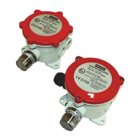
- Page 1 Operation Manual Series 47K Gas Detector [SIL 2] Order No.: 10052472/14 MSAsafety.com...
- Page 2 For the Declaration of Conformity, please visit the product page on MSAsafety.com. Schlüsselstrasse 12 8645 Rapperswil-Jona Switzerland © MSA 2016. All rights reserved...
-
Page 3: Table Of Contents
CONTENTS Contents Safety Regulations ....................6 1.1. Correct Use ....................6 1.2. Liability Information ..................6 1.3. Application, Advice and Restrictions ............7 Description ......................8 2.1. General ...................... 8 ... - Page 4 Ordering Information ..................34 8.1. Gas Detector (Sensor + Junction Box) ............. 34 8.2. Gas Detector, Calibrated with Certified MSA Gas Controllers ....34 8.3. Sensor ...................... 34 8.4. Junction Box ..................... 35 ...
- Page 5 Series 47K-PRP/-HT-PRP [3-wire] ..............43 10.1.2 Series 47K-PRP/-HT-PRP [5-wire] ..............44 10.2. MSA Control Unit 9010 / 9020 Series ............44 10.2.1 Series 47K-PRP/-HT-PRP [3-wire] Channel A ..........44 10.2.2 Series 47K-PRP/-HT-PRP [3-wire] Channel B ..........45 ...
-
Page 6: Safety Regulations
0 to 100% LEL. It is designed for use as an integral part of an MSA fixed gas detection system for the protection of industrial plant and workers. -
Page 7: Application, Advice And Restrictions
The only method of verifying the correct operation of the sensor is to carry out a span check using a known concentration of calibration gas in air. For response curves contact your national MSA office. Series 47K Gas Detector [SIL 2]... -
Page 8: Description
0 to 100% LEL. It is designed for use as an integral part of an MSA fixed gas detection system for the protection of industrial plant and workers. -
Page 9: Principle Of Operation
DESCRIPTION 2.2. Principle of Operation The MSA 47K series of sensors operate on the principle of catalytic combustion. The sensing element consists of a pair of filaments [“pellistors”] connected to a pair of precision resistors to form a Wheatstone bridge. - Page 10 DESCRIPTION Operating temperature range PRP- sensor -25 °C to +55 °C Extended range *) -40 °C to +55 °C HT-PRP sensor -40 °C to +160 °C Operating humidity range 5% to 95% RH non-condensing Operating pressure range 800–1200 hPa Air velocity Air velocity 0–6 m/s [with duct mount flange: 0.5–20 m/s] Poison resistance...
-
Page 11: Installation
(1) Unpack and inspect the device or its components. (2) Check the suitability of the installation site and the cabling requirements. (3) Install the sensors and connect the wiring to the MSA control unit. (4) The installation of the sensor must be performed according to standard EN 60079-14 or according to applicable national standards. -
Page 12: Recommended Torque And Terminal Sizes
The specified environmental conditions must be adhered to. Position the height of the MSA Gas detector Series 47K according to the density of gas or vapour to be measured. The proper installation location must be chosen to ensure that the sintered ... -
Page 13: Electrical Connection To The Control Unit
The maximum cable length depends on the maximum permissible load, the cross section of the conductor and the conductor material. The maximum permissible load [loop resistance] is 36 ohms for the MSA Control units SUPREMA [for MSA Control unit 9010/9020 refer to the control unit manual]. -
Page 14: Electrical Connections
regulations should be complied with especially in places where there is a risk of explosion and fire. [Classified areas] Refer to the MSA controller instruction manual for the sensor connection details. Where an earth connection to the junction box/sensor is required use the ... -
Page 15: Maintenance And Service
MAINTENANCE AND SERVICE Maintenance and Service There are no serviceable or adjustable parts within the sensor assembly and any attempt to dismantle the assembly or access it will invalidate the sensor approvals and manufacturers guarantee. Maintenance and service may only be performed by authorised and suitably qualified personnel. -
Page 16: Zero Calibration
MAINTENANCE AND SERVICE 5.1.1 Zero Calibration Apply zero gas to the sensor using the appropriate calibration adapter. Wait for approximately 2 minutes or until the sensor reading has stabilised. Adjust the controller until the correct reading is obtained. ... -
Page 17: Sensor Replacement
MAINTENANCE AND SERVICE 5.2. Sensor Replacement Caution In a hazardous area, ensure all necessary precautions are taken before opening the junction box. Replacement of the sensor or other parts should only be carried out by suitably qualified personnel. After checking if it is possible to carry out operation, according to the type of danger in the area where the gas detector is installed, proceed as follows: (1) Disconnect the power supply to the gas detector at the Control unit. -
Page 18: Series 47K-Prp And Series 47K-Ht-Prp
MAINTENANCE AND SERVICE 5.3. Series 47K-PRP and Series 47K-HT-PRP For the gases or vapours shown in the tables of Section 5.3.1 and 5.3.2 the response curves have been tested according to EN 61779-1. If the LEL of a substance was not listed in EN 61779-1, the LEL has been taken from the Chemsafe data base [Dechema, Frankfurt]. -
Page 19: Ht-Prp
MAINTENANCE AND SERVICE 5.3.1 47K-HT-PRP Relative response factors of tested gases with reference to Propane. These values are only valid for new sensors and, unless otherwise stated, refer to an ambient temperature of 110 °C. In this case the displayed values may vary by up to ±20% from the target gas concentration. - Page 20 MAINTENANCE AND SERVICE 100% Propane relative Response Response Sample gas response factor time [secs] time [secs] in vol% 1.48 ²) i-Butyl acetate 1.56 ²) n-Butyl acetate 3.85 ²) Butylbenzene 0.93 ²) i-Butylene 1.49 ²) Cyclohexane 1.05 ²) Cyclopentane 1,16 ²) Diethylether 2.22 ²) 1.4-Dioxane...
- Page 21 These are not included in the EC-Type Examination Certificates DMT 01 ATEX G 001 X, BVS 03 ATEX G 010 X und DMT 03 ATEX G 003 X These gases may not be used with the MSA Gasgard XL Controller, since these can trigger pre-alarms at high ambient temperatures.
-
Page 22: Accessories
ACCESSORIES Accessories 6.1. Calibration Cap The calibration cap is pushed on to the front of the sensor and is sealed by an “O” ring. The surface area S < 20 cm Warning The calibrating cap must be removed after completing the calibration! The gas is supplied via either of the gas inlets by means of suitable flexible tube. -
Page 23: Flow Through Adapter / Pump Adapter
ACCESSORIES The stainless steel versions are available with hose or pipe connection for remote calibration. Pipe connection : 1/8” NPT Gas flow rate : 1.0 l/min Air velocity : 0 ... 6 m/s Calibration must only be carried out if wind speed is < 1.5 m/s. Using the Weather Protection Cap will extend the response time to: <... -
Page 24: Duct Mount Flange
ACCESSORIES 6.4. Duct Mount Flange Gas monitoring in air ducts can be performed by means of this duct mount flange. When installing it the direction of flow inside the duct must be towards the baffle as shown in the photograph. The sensor can be calibrated via the gas calibration port, provided the duct is free of all gases to which the sensor will respond. -
Page 25: Pipe Mounting Kit
ACCESSORIES 6.5. Pipe Mounting Kit Note: The pipe mounting kit (P/N 10 113032) is not included in the EC-Type Examination Certificates DMT 01 ATEX G 001 X, BVS 03 ATEX G 010 X and DMT 03 ATEX G 003 X 6.5.1 Mounting Kit for Pipes with a Diameter of up to 50 mm The S 47K-PRP can be mounted vertically by fastening its legs by means of three screws. -
Page 26: Mounting Kit For Pipes With A Diameter From 50 Mm To 150 Mm
ACCESSORIES 6.5.2 Mounting Kit for Pipes with a Diameter from 50 mm to 150 mm Mounting plate Pipe clamps 6.6. Remote Calibration Adaptor (CalGard) Series 47K Gas Detector [SIL 2]... -
Page 27: Installation
ACCESSORIES Note: Operating the remote calibration adaptor CalGard together with the gas detector model S 47K-PRP is included in the EC-Type Examination Certificates DMT 01 ATEX G 001 X, BVS 03 ATEX G 010 X and DMT 03 ATEX G 003 X. The CalGard stainless steel remote calibration adaptor provides reliable operation of remotely installed gas detectors working under harsh environmental conditions. -
Page 28: Operation
-30 °C to +70 °C Maximum wind speed: up to 6 m/s Applicable test gases: , CH in air (approval of other gases by MSA on request) Recommended flow rate: 1.0 l / min Minimum flow rate: 0,8 l / min Maximum flow rate: 1.5 l / min... -
Page 29: Markings, Certificates And Approvals
MARKINGS, CERTIFICATES AND APPROVALS Markings, Certificates and Approvals 7.1. According to the Directive 2014/34/EU [ATEX] 7.1.1 Series 47K-PRP, Series 47K-HT-PRP Manufacturer : MSA Europe GmbH, Schlüsselstr. 12, CH - 8645 Rapperswil-Jona Product : Remote Head SERIE 47 K EC-Type : Ex Sensor... -
Page 30: Junction Box Typ S47K And X Series Al Junction Box
EN 60079-0 :2012 + A11 :2013, EN 60079-1 :2014, EN 60079-7 :2007, EN 60079-31 :2014 Performance see MSA Controller together with sensor serie 47K Marking cable gland: NPT ¾” or M25 x 1,25 II 2G Ex db IIC T4/T6 Gb II 2G Ex e IIC T4/T6 Gb II 2D Ex tb IIIB T85 °C / T135 °C Db IP6X... -
Page 31: According To Iecex
MARKINGS, CERTIFICATES AND APPROVALS 7.2. According to IECEx Manufacturer MSA Europe GmbH, Schlüsselstr. 12, CH - 8645 Rapperswil-Jona Product Junction Box Typ S47K and X Series AL Junction Box IECEx-Type IECEx BVS 12.0057 X Examination Certificate Standards IEC 60079-0 :2011, IEC 60079-1 :2014,... -
Page 32: Special Conditions For Sil 2 According To Tuv Certificate 968 / Ez 392.00/09
MARKINGS, CERTIFICATES AND APPROVALS 7.3. Special Conditions for SIL 2 According to TUV Certificate 968 / EZ 392.00/09 Safety relevant parameters for Sensor Type 47K-PRP at 25 °C and for 47K-HT-PRP at 120 °C Type Structure 1oo1 1,3 x 10 1,9 x 10 75,8% MTBF... - Page 33 The Control Unit has to activate an alarm by a single sensor. A defective sensor must be changed within 72 hours. The safety related specifications for the MSA passive sensors Series 47K are only valid when used in combination with certified MSA Controllers.
-
Page 34: Ordering Information
Ex e 10114109 Spring terminals Detector Series 47K-PRP ¾“ NPT Ex d 10114110 Spring terminals 8.2. Gas Detector, Calibrated with Certified MSA Gas Controllers Description Thread Part-No. Detector Series 47K-PRP M25 x 1.5 10123076 Screw terminals Detector Series 47K-PRP M25 x 1.5... -
Page 35: Junction Box
ORDERING INFORMATION 8.4. Junction Box Description Material For use with Sensor Part-No. Ex e, 2 x M25 x 1.5 Aluminium 47K-PRP 10114111 Screw terminals Ex e, 2 x M25 x 1.5 Aluminium 47K-PRP 10114114 Spring terminals Ex e, 2 x M25 x 1.5, Aluminium 47K-PRP 10114113... -
Page 36: Dimensions
DIMENSIONS Dimensions 9.1. Gas Detector (Ex e Junction Box) Series 47K Gas Detector [SIL 2]... -
Page 37: Gas Detector (Ex D Junction Box)
DIMENSIONS 9.2. Gas Detector (Ex d Junction Box) Series 47K Gas Detector [SIL 2]... -
Page 38: S47K Adapter Plate (Junction Box)
DIMENSIONS 9.3. S47K Adapter Plate (Junction Box) 9.4. Wall Mounted Bracket, Sensor 47K-HT-PRP Series 47K Gas Detector [SIL 2]... -
Page 39: Junction Box Atex 100 °C; Sensor 47K-Ht-Prp
DIMENSIONS 9.5. Junction Box ATEX 100 °C; Sensor 47K-HT-PRP Series 47K Gas Detector [SIL 2]... -
Page 40: Pipe Mounting Kit
DIMENSIONS 9.6. Pipe Mounting Kit 9.6.1 Mounting Kit for Pipes with a Diameter of up to 50 mm Pipe Pipe clamp Mounting plate Depending on pipe diameter Series 47K Gas Detector [SIL 2]... -
Page 41: Mounting Kit For Pipes With A Diameter From 50 Mm To 150 Mm
DIMENSIONS 9.6.2 Mounting Kit for Pipes with a Diameter from 50 mm to 150 mm Pipe Pipe clamp Mounting plate Series 47K Gas Detector [SIL 2]... -
Page 42: Remote Calibration Adaptor
DIMENSIONS 9.7. Remote Calibration Adaptor Series 47K Gas Detector [SIL 2]... -
Page 43: Wiring Diagrams
WIRING DIAGRAMS 10. Wiring Diagrams 10.1. MSA Control Unit SUPREMA Attention The fault signals required in EN 60079-29-1 for loss of continuity or short circuit of one or more wires to the remote sensor are not provided with a 3 wire connection. A 5 wire connection is therefore recommended. -
Page 44: Series 47K-Prp/-Ht-Prp [5-Wire]
Information regarding the 5-wire wiring of the -HT-PRP can be found in chapter 10.5. SUPREMA Sensor type: MAT-TS-Module Series 47K-PRP/-HT-PRP 10.2. MSA Control Unit 9010 / 9020 Series 10.2.1 Series 47K-PRP/-HT-PRP [3-wire] Channel A [47K-HT-PRP see chapter 10.4] Terminal block Sensor type: 9010 / 9020... -
Page 45: Series 47K-Prp/-Ht-Prp [3-Wire] Channel B
10.2.2 Series 47K-PRP/-HT-PRP [3-wire] Channel B [for 47K-HT-PRP see chapter 10.4] Terminal block Sensor type: 9020 Series 47K-PRP/-HT-PRP Channel 10.3. MSA Control Unit Gasgard XL 10.3.1 Series 47K-PRP [3-wire] GasGard XL Mainboard Terminal Series 47K-PRP Series 47K Gas Detector [SIL 2]... -
Page 46: Series 47K-Ht-Prp
WIRING DIAGRAMS 10.3.2 Series 47K-HT-PRP GasGard XL Series 47K-HT-PRP Mainboard Terminal 10.4. Wiring Diagram Sensor 47K-HT-PRP with Junction Box ATEX 100 °C Terminal block Sensor type Series 47K-HT-PRP Brown Grey Black White on wall mounted bracket Series 47K Gas Detector [SIL 2]... -
Page 47: Appendix
APPENDIX 11. Appendix 11.1. Discontinued Gas Detectors 11.1.1 47K-ST Relative response factors of tested gases with reference to Propane. These values are only valid for new sensors and, unless otherwise stated, they refer to an ambient temperature of 20 °C. In this case the displayed values may vary by up to ±20% from the target gas concentration. -
Page 48: K-Ht
APPENDIX 11.1.2 47K-HT Relative response factors of tested gases with reference to Propane. These values are only valid for new sensors and, unless otherwise stated, refer to an ambient temperature of 110 °C. In this case the displayed values may vary by up to ±20% from the target gas concentration. - Page 49 APPENDIX Notes Series 47K Gas Detector [SIL 2]...
- Page 50 APPENDIX Notes Series 47K Gas Detector [SIL 2]...
- Page 51 APPENDIX Notes Series 47K Gas Detector [SIL 2]...
- Page 52 For local MSA contacts, please visit us at MSAsafety.com Because every life has a purpose...
Need help?
Do you have a question about the 47K Series and is the answer not in the manual?
Questions and answers