
Related Manuals for Dialog Semiconductor DA14695 ProDK


Summary of Contents for Dialog Semiconductor DA14695 ProDK
- Page 1 User Manual DA1469x Getting Started Guide with the Development Kit UM-B-090 The focus of this User Manual is to easily introduce the DA1496x Getting started guide with the development kit.
-
Page 2: Table Of Contents
Building a DA14695 Application – Advertising Demo ............. 34 Introduction ......................... 34 Software Architecture ......................34 Software Build ........................35 9.3.1 Build the project to run from RAM ............... 36 User Manual Revision 1.0 24-Feb-2019 CFR0012 2 of 46 © 2019 Dialog Semiconductor... -
Page 3: Figures
14 RoHS Compliance ........................46 Figures Figure 1: The DA1469x Product Family ....................7 Figure 2: The DA14695 ProDK DK ....................... 8 Figure 3: Main board - daughter board alignment ................. 9 Figure 4: The DA14695 daughter board Layout ..................9 Figure 5: ProDK Development Kit Jumper setting ................ -
Page 4: Tables
Figure 48: Write binary to the QSPI Flash using cli_programmer ............43 Figure 49: PRO-Mainboard breakout headers ..................44 Tables Table 1: The DA14695 ProDK main elements ..................8 Table 2: DA14695 Daughter Board main elements ................10 Table 3: Default jumper settings ......................11 Table 4: Parameters for connecting to UART2 ................... -
Page 5: Abstract
The DA14695x is a family of wireless MCU dual core ARM + M0+. It is the World’s Most Advanced Wireless SOC. Comparing to DA1468x, the DA1469x has: • 2x Processing power • 2x Battery lifetime User Manual Revision 1.0 24-Feb-2019 CFR0012 5 of 46 © 2019 Dialog Semiconductor... -
Page 6: Guide Purpose
This tutorial requires 45-60 minutes to complete. For more information the user may consult the accompanied documentation these are mentioned as for further reading. Kit Content The DA14695 ProDK Kit parts can be ordered via various distributors. The DA14695 Pro Development Kit contains the following: •... -
Page 7: Da1469X - The Hardware
USB based debugging capabilities using the SEGGER J-Link on-board debugger for Cortex M33. • USB based UART communication with the host PC using a Future Technology Devices International (FTDI FT2232H) chipset which converts UART to USB. User Manual Revision 1.0 24-Feb-2019 CFR0012 7 of 46 © 2019 Dialog Semiconductor... -
Page 8: Figure 2: The Da14695 Prodk Dk
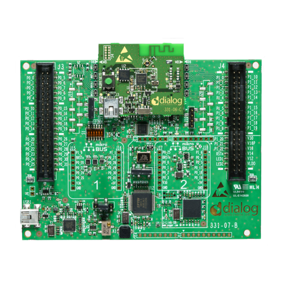
UM-B-090 DA1469x Getting Started Guide with the Development Kit Figure 2: The DA14695 ProDK DK Table 1: The DA14695 ProDK main elements Reference Description U12: FTDI Chip User button (K1) Arduino sockets Trimmer to define the adjustable LDO voltage (R127) -
Page 9: The Prodk Daughter Board
Figure Figure 3: Main board - daughter board alignment Figure 4 presents the DA14695 daughter board Layout. Figure 4: The DA14695 daughter board Layout User Manual Revision 1.0 24-Feb-2019 CFR0012 9 of 46 © 2019 Dialog Semiconductor... -
Page 10: Configuring The Pro Kit Main Board By Jumper Settings
Li-Ion/LiPo/coin Battery • USB connector • CIB interface (providing also JTAG/UART debugging functions) Configuring the Pro Kit main Board by Jumper Settings The jumper settings are displayed below: User Manual Revision 1.0 24-Feb-2019 CFR0012 10 of 46 © 2019 Dialog Semiconductor... -
Page 11: Connecting The Prodk To The Host Pc
The ProDK Development Kit is connected to the host PC over the connector marked as USB1, as shown in reference 6 in Figure 2 Figure 6 using a standard mini-USB cable. For further reading User Manual Revision 1.0 24-Feb-2019 CFR0012 11 of 46 © 2019 Dialog Semiconductor... -
Page 12: Da14695 Connecting The Board
For proper evaluation and application development using the DA14695 SoC and the ProDK an external host is required. This external host must have an operating system already installed (Windows or Linux) and USB ports as described in 2. User Manual Revision 1.0 24-Feb-2019 CFR0012 12 of 46 © 2019 Dialog Semiconductor... -
Page 13: Driver Installation
ProDK Kit board and the Windows on that port. But you can do it only by using the other lowest COM port, COM25 in this case. User Manual Revision 1.0 24-Feb-2019 CFR0012 13 of 46 © 2019 Dialog Semiconductor... -
Page 14: Linux
/dev/ttyUSB0. If there are more devices with the name ttyUSBx, note which ones showed up when the ProDK was connected and use the lower number of the two devices. User Manual Revision 1.0 24-Feb-2019 CFR0012 14 of 46 © 2019 Dialog Semiconductor... -
Page 15: Com Port Usage
Open Tera Term from the Windows Start menu. • Step 4 In the Tera Term: New connection dialog, select Serial, then select the COM Port to use, and click OK. User Manual Revision 1.0 24-Feb-2019 CFR0012 15 of 46 © 2019 Dialog Semiconductor... -
Page 16: Figure 10: Terminal Output Via Tera Term (Windows)
Figure 10. The DA1496X device use random BLE addresses, new address is generated on every reset button push. Figure 10: Terminal output via Tera Term (Windows) User Manual Revision 1.0 24-Feb-2019 CFR0012 16 of 46 © 2019 Dialog Semiconductor... -
Page 17: Linux Host
Once you have a connection, you should start to see something as shown in Figure 12. This is the output under Linux with putty. Figure 12: Terminal output via putty (Linux User Manual Revision 1.0 24-Feb-2019 CFR0012 17 of 46 © 2019 Dialog Semiconductor... -
Page 18: Troubleshooting
SmartSnippets™ Studio Installation and Starting This section describes the installation of SmartSnippets™ Studio. For further reading the installation procedure is described in detail in UM-B-057 SmartSnippets Studio User Manual. User Manual Revision 1.0 24-Feb-2019 CFR0012 18 of 46 © 2019 Dialog Semiconductor... -
Page 19: Windows
Select the recommended version or a newer one from of SEGGER J-Link GDB server and Click Next. Figure 13: Automatically install J-Link • Select the destination folder for the SmartSnippets™ Studio and click "Next". The default installation location C:/DiaSemi is recommended User Manual Revision 1.0 24-Feb-2019 CFR0012 19 of 46 © 2019 Dialog Semiconductor... -
Page 20: Figure 14: Select Smart Snippets Studio Install Directory
When SmartSnippets™ Studio starts for the first time, the user must configure it. The necessary configurations are the following: • Select the workspace folder for SmartSnippets™ Studio. This should be the created directory inside workspace_SmartSnippets_Studio. User Manual Revision 1.0 24-Feb-2019 CFR0012 20 of 46 © 2019 Dialog Semiconductor... -
Page 21: Figure 16: Sdk Tools Summary
Skip button will show • The Next button is enabled only after the mandatory tools are successfully installed or a valid installation path is specified. User Manual Revision 1.0 24-Feb-2019 CFR0012 21 of 46 © 2019 Dialog Semiconductor... -
Page 22: Figure 17: Start Ozone Download
Download. After the download is complete, the green completion mark appears. Then press the Next button to continue as shown in Figure User Manual Revision 1.0 24-Feb-2019 CFR0012 22 of 46 © 2019 Dialog Semiconductor... -
Page 23: Figure 19: Gcc Tools Installation
The user’s choice to skip an optional tool is remembered by SmartSnippets™ Studio so that the wizard does not ask again for the installation of this tool the next time the wizard is launched. User Manual Revision 1.0 24-Feb-2019 CFR0012 23 of 46 © 2019 Dialog Semiconductor... -
Page 24: Linux
• The first step is to make the SmartSnippets™ Studio installer executable. • $chmod a+x SmartSnippets_Studio-linux.gtk.x86_64-1.6.3.run • And then run it. • $./SmartSnippets_Studio-linux.gtk.x86_64-1.6.3.run User Manual Revision 1.0 24-Feb-2019 CFR0012 24 of 46 © 2019 Dialog Semiconductor... -
Page 25: Figure 22: Automatically Install The J-Link
Figure 22: Automatically install the J-Link • Select the destination folder for the SmartSnippets™ Studio Figure 23: Select SmartSnippets™ Studio install directory • The installation of the SmartSnippets™ Studio will then start. User Manual Revision 1.0 24-Feb-2019 CFR0012 25 of 46 © 2019 Dialog Semiconductor... -
Page 26: Figure 24: Sdk Tools Summary (Linux)
This will install the tool to /opt/SEGGER/ozone/2.60c. Use the Browse button to find this folder and then press Next. Figure 25: Set the Ozone installation directory • Then, the installer will guide user to install SEGGER JLink. User Manual Revision 1.0 24-Feb-2019 CFR0012 26 of 46 © 2019 Dialog Semiconductor... -
Page 27: Figure 26: Set Segger J-Link Installation Directory
Then, the installer will guide user to install GCC. Browse button to find this folder and then press Next. Figure 27: GCC Installation directory • The final stage is to install SEGGER SystemView. User Manual Revision 1.0 24-Feb-2019 CFR0012 27 of 46 © 2019 Dialog Semiconductor... -
Page 28: Package Structure And Folders
Studio so that the wizard does not ask again for the installation of this tool the next time the wizard is launched. Figure 29: Installed tools summary under Linux Package structure and Folders The directory structure of the SDK is shown in Figure 30. User Manual Revision 1.0 24-Feb-2019 CFR0012 28 of 46 © 2019 Dialog Semiconductor... -
Page 29: Extracting And Using The Sdk
SDK zip file as there is no longer a clean copy of the SDK on which to base new projects. User Manual Revision 1.0 24-Feb-2019 CFR0012 29 of 46 © 2019 Dialog Semiconductor... -
Page 30: Additional Software
Programmer. The CLI Programmer is a command line tool for programming the DA14695 family of devices. It allows erasing and programming the device Flash or OTP memory. This tool may be used User Manual Revision 1.0 24-Feb-2019 CFR0012 30 of 46 © 2019 Dialog Semiconductor... -
Page 31: Run The Pre-Loaded Demo
On the daughter board, Red LED 1 is blinking – On the main board Blue LED D1, Green LED 4 and Green LED 5 are ON. Figure 33: LEDs Status User Manual Revision 1.0 24-Feb-2019 CFR0012 31 of 46 © 2019 Dialog Semiconductor... -
Page 32: Figure 34: Pre-Loaded Demo: Interacting With Ble Application
33. You can write value to Alert Level characteristic in Immediate Alert service: – 0x00 (No alert) - the white LED on ProDK device does not blink User Manual Revision 1.0 24-Feb-2019 CFR0012 32 of 46 © 2019 Dialog Semiconductor... -
Page 33: Figure 35: Pre-Loaded Demo: Alerting Manual Testing
0x01 (Mild alert) - the white LED on ProDK blinks slow immediately – 0x02 (High Alert) - the white LED on ProDK blinks fast immediately Figure 35: Pre-Loaded Demo: Alerting Manual testing User Manual Revision 1.0 24-Feb-2019 CFR0012 33 of 46 © 2019 Dialog Semiconductor... -
Page 34: Building A Da14695 Application - Advertising Demo
0, NULL); /* Start advertising */ ble_gap_adv_start(GAP_CONN_MODE_UNDIRECTED); (;;) { ble_evt_hdr_t *hdr; /* Notify watchdog on each loop */ sys_watchdog_notify(wdog_id); /* Suspend watchdog while blocking on ble_get_event() */ sys_watchdog_suspend(wdog_id); User Manual Revision 1.0 24-Feb-2019 CFR0012 34 of 46 © 2019 Dialog Semiconductor... -
Page 35: Software Build
1. In the SmartSnippets™ Studio welcome page click on the IDE icon from the Tools tab as shown in Figure 6 Figure 36: SmartSnippets™ Studio welcome page User Manual Revision 1.0 24-Feb-2019 CFR0012 35 of 46 © 2019 Dialog Semiconductor... -
Page 36: Build The Project To Run From Ram
QSPI Flash, the debugger will load it directly into RAM from where it can be run. This is not the normal method of development. Build the project with the Build button and select Debug RAM configuration DA1469X-00-Debug- RAM as shown in Figure 38. User Manual Revision 1.0 24-Feb-2019 CFR0012 36 of 46 © 2019 Dialog Semiconductor... -
Page 37: Figure 38: Build Adv Ble In Debug Ram Configuration
39. As this is a RAM build the debugger will download the binary file via J-Link debugger into the system RAM. To enable this the system RAM is mapped to address 0 by the debugger. Figure 39: Start Debug in RAM mode User Manual Revision 1.0 24-Feb-2019 CFR0012 37 of 46 © 2019 Dialog Semiconductor... -
Page 38: Build The Project To Run From Qspi Flash
QSPI Flash the External Tool button. In Figure 41 memory. Alternatively, use Run > External Tools > program_qspi_jtag. Figure 41: Write ADV BLE to QSPI Flash User Manual Revision 1.0 24-Feb-2019 CFR0012 38 of 46 © 2019 Dialog Semiconductor... -
Page 39: Configure Smartsnippets™ To Write To Flash
Figure 41. This will open the window as shown in Figure 43 with a summary of the current QSPI configuration and supported device. Figure 43: Configuration Summary User Manual Revision 1.0 24-Feb-2019 CFR0012 39 of 46 © 2019 Dialog Semiconductor... -
Page 40: Figure 44: Select Product Id
Finally, you will be asked to insert an address about: Active FW image address and Update FW image address. Please keep in both entries the default value 0x2000. Warning User Manual Revision 1.0 24-Feb-2019 CFR0012 40 of 46 © 2019 Dialog Semiconductor... -
Page 41: Running The Project In The Debugger
Figure 46: Executing the ADV BLE project in SmartSnippets™ The correct functionality of the ADV BLE project can be checked by noticing in the BLE scanner application. User Manual Revision 1.0 24-Feb-2019 CFR0012 41 of 46 © 2019 Dialog Semiconductor... -
Page 42: How To Program The Original Fw Back Into The Qspi Flash
Build the project to run from QSPI Flash or you can compile it and write the built .bin to the Flash using <sdk_root_directory>/binaries/cli_programmer.exe as shown in Figure 48. Code 2 Command to Write binary to the QSPI Flash using cli_programmer ./cli_programmer.exe gdbserver write_qspi pro_kit_demo.bin User Manual Revision 1.0 24-Feb-2019 CFR0012 42 of 46 © 2019 Dialog Semiconductor... -
Page 43: What Is Next
DA1496X: • : To know more about the SmartBond™ DA1469x SoC. DA1469x Product Brief • UM-B-092: DA1469x Software Platform Reference : To know more about software architecture. User Manual Revision 1.0 24-Feb-2019 CFR0012 43 of 46 © 2019 Dialog Semiconductor... -
Page 44: 10 Appendices
UM-B-090 DA1469x Getting Started Guide with the Development Kit 10 Appendices 10.1 Appendix A: Figure 49: PRO-Mainboard breakout headers User Manual Revision 1.0 24-Feb-2019 CFR0012 44 of 46 © 2019 Dialog Semiconductor... -
Page 45: 11 Revision History
Standard Terms and Conditions of Sale, available on the company website (www.dialog-semiconductor.com) unless otherwise stated. Dialog and the Dialog logo are trademarks of Dialog Semiconductor plc or its subsidiaries. All other product or service names are the property of their respective owners. -
Page 46: 14 Rohs Compliance
DA1469x Getting Started Guide with the Development Kit 14 RoHS Compliance Dialog Semiconductor complies to European Directive 2001/95/EC and from 2 January 2013 onwards to European Directive 2011/65/EU concerning Restriction of Hazardous Substances (RoHS/RoHS2). Dialog Semiconductor’s statement on RoHS can be found on the DA1496x RoHS 2 declaration.
Need help?
Do you have a question about the DA14695 ProDK and is the answer not in the manual?
Questions and answers