Table of Contents
Advertisement
Quick Links
Advertisement
Table of Contents

Related Manuals for Sunny Health & Fitness SF-RW5864


Summary of Contents for Sunny Health & Fitness SF-RW5864
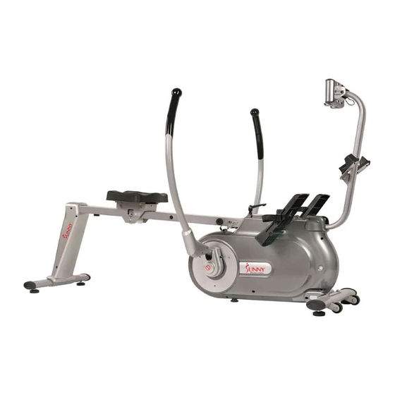
- Page 1 MAGNETIC ELLIPTICAL TRAINER SF-RW5864 USER MANUAL IMPORTANT! Please retain owner’s manual for maintenance and adjustment instructions. Your satisfaction is very important to us, PLEASE DO NOT RETURN UNTIL YOU HAVE CONTACTED support@sunnyhealthfitness.com or 1- 877 - 90SUNNY (877-907-8669).
-
Page 2: Important Safety Information
IMPORTANT SAFETY INFORMATION We thank you for choosing our product. To ensure your safety and health, please use this equipment correctly. It is important to read this entire manual before assembling and using the equipment. Safe and effective use can only be achieved if the equipment is assembled, maintained, and used properly. It is your responsibility to ensure that all users of the equipment are informed of all warnings and precautions. -
Page 3: Exploded Diagram
EXPLODED DIAGRAM... -
Page 4: Hardware Package
HARDWARE PACKAGE #26 d8*Φ16*1.5 8PCS #25 M8*20*S6 4PCS #24 M12*Φ12.5*160*23*S19 #77 Φ14*44*M12*18 4PCS 2PCS #40 Φ33*Φ8*13 1PC #72 M12*H11*S19 2PCS #42 M6*16*Φ12 1PC #41 d6*Φ12*1.2 1PC #46 d8 4PCS #128 M8*16*S6 4PCS #61 ST4.2*19*Φ8 2PCS #60 M4*10*Φ6 4PCS #36 ∅10*95*M6*25 1PC #17 111*22*96 1PC #38 ∅10*100*105 1PC #37 M6*16*S5 1PC... -
Page 5: Parts List
PARTS LIST Description Spec. Qty. Description Spec. Qty. ∅10*95*M6*25 Computer Bolt Computer Seat Bolt M6*16*S5 ∅10*100*105 Screw Φ12*80*M6 Bolt M8*90*20*S13 Limited Shaft d8*Φ16*1.5 Φ33*Φ8*13 Foot Pad Washer d6*Φ12*1.2 M8*H7.5*S13 Washer Computer Joint M6*16*Φ12 Screw Tube Φ16 Shaft Sleeve Grommet Plug 9L/R Rowing Rod Pad Inductor... - Page 6 Description Spec. Qty. Description Spec. Qty. Magnet Fixed Cover Plate M12*H11*S19 Copper Bush d12*Φ32*2.0 M6*20*Φ10.5 Washer Screw Magnet Fixed Φ52*15*Φ25 Bearing Plate Φ25*10 Screw M5*5 Magnet 76L/ Shaft Sleeve Spring Washer Combination Φ14*44*M12*18 Bolt Bolt M6*12*S10 ST4.2*19*Φ8.4 M5*10*Φ10 Screw Screw Strong Magnet Rowing Rod Connecting Plate...
-
Page 7: Assembly Instructions
ASSEMBLY INSTRUCTIONS STEP 1: Attach Front Stabilizer (No. 27) to Main Frame (No. 13) with 2 Bolts (No. 25) and 2 Washers (No. 26). Tighten and secure with the Allen Wrench (No. B). STEP 2: #24 M12*Φ 12.5*160*23*S19 4PCS Loosen T Knob (No. 22) as shown in figure C A position and pull outward. - Page 8 STEP 3: Remove 4 Screws (No. 60) from Shaft Sleeve Combination (No. 76L/R) with Spanner (No. A). Put Rowing Rods (No. 79) into Shaft Sleeve Combinations (No. 76L/R) with 2 Bolts (No. 77) and 2 Nuts (No. 72). Tighten and secure with Spanner (No. D). Note: The Bolt (No.
- Page 9 STEP 5: Attach Rear Supporting Tube (No. 132) to Iron Rail (No. 35) with 4 Bolts (No. 128), 4 Spring Washers (No. 46), and 4 Washers (No. 26). Tighten and secure with the Allen Wrench (No. B). Attach Rear Stabilizer (No. 34) to Rear Supporting Tube (No.
- Page 10 STEP 7: Attach Iron Rail (No. 35) to Main Frame (No. 13) using Bolt (No. 36) and Bolt (No. 37). Tighten and secure with Allen Wrench (No. B) and Allen Wrench (No. C). Then insert Pin (No. 38). #B S6 #C S5 Next, attach the top of Iron Rail (No.
-
Page 11: Adjustment Guide
ADJUSTMENT GUIDE PEDAL STRAP ADJUSTMENT Figure A Pull The Pedal Strap (No. 137) is adjustable and can Push be personalized to fit the user’s foot size. Directions on how to loosen and tighten the straps are shown Figure B in figures A and B. Pull MOVING THE MACHINE To move the machine, lift up Rear Stabilizer (No. -
Page 12: Adjusting The Balance
ADJUSTMENT GUIDE ADJUSTING THE RESISTANCE OF THE ROWING ROD The resistance is different at positions A, B, C, etc. The closer you are to positions A, the lighter the resistance. ADJUSTING THE BALANCE In order to achieve a smooth and comfortable ride, you must ensure that the stability of the machine is secured. - Page 13 ADJUSTMENT GUIDE When not in use, you can save space by folding the Iron Rail Loosen (No. 35). 1. Unscrew L Knob (No. 17), Fasten unplug Pin (No. 38), and then flip Iron Rail (No. 35) together forming a vertical angle.
-
Page 14: Exercise Computer
EXERCISE COMPUTER KEY FUNCTIONS: MODE: Press this button to change the display or to choose a program. SET: MODE RESET In the setting mode, press this button to increase the setting value for TIME,COUNT, and CAL. RESET: 1. In setting mode, press this button to reset the value for TIME, COUNT, and CAL. 2. -
Page 15: Operation
OPERATION: SET: Press MODE to choose the display window that needs to be pre-set. Press SET to increase the value to reach your desired time, calorie, or count. Hold SET to increase the value. Press RESET to reset values. BATTERY REPLACE: When the display screen light begins to fade, remove the battery and replace with SIZE AAA, UM4, R03.
Need help?
Do you have a question about the SF-RW5864 and is the answer not in the manual?
Questions and answers