Sign In
Upload
Manuals
Brands
Leuze electronic Manuals
Barcode Reader
BCL348i
Leuze electronic BCL348i Manuals
Manuals and User Guides for Leuze electronic BCL348i. We have
2
Leuze electronic BCL348i manuals available for free PDF download: Technical Description, Manual
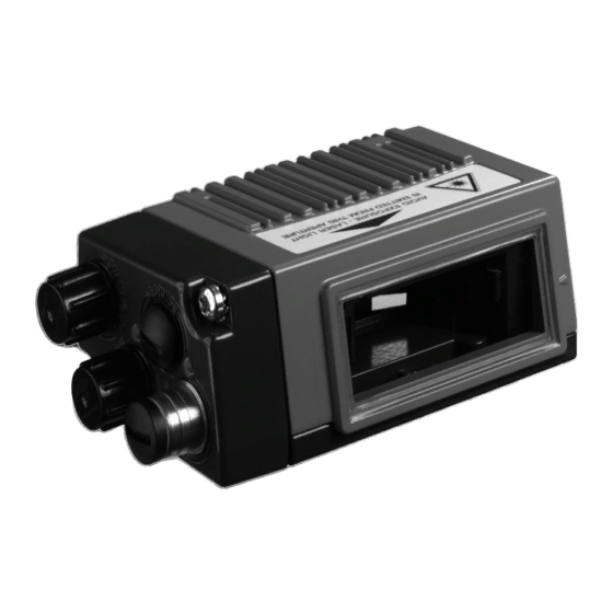
Leuze electronic BCL348i Technical Description (216 pages)
Brand:
Leuze electronic
| Category:
Barcode Reader
| Size: 15 MB
Table of Contents
Table of Contents
3
1 General Information
13
Explanation of Symbols
13
Declaration of Conformity
13
2 Safety Notices
14
General Safety Notices
14
Safety Standards
14
Approved Purpose
14
Working Safely
15
Figure 2.1: Attachment of the Stick-On Labels with Warning Notices at the BCL 348I
16
3 Fast Commissioning / Operating Principle
17
Device Arrangement and Selection of the Mounting Location
17
Mounting the BCL 348I
17
Electrical Connectionbcl 348I
18
Figure 3.1: BCL 348 I - MS 348 Hood with Integrated M12 Connectors
18
Figure 3.2: BCL 348 I - MK 348 Terminal Hood with Spring-Loaded Terminals
19
Figure 3.3: Cable Fabrication for MK 308 Terminal Hood
19
Commissioning the BCL 348 I on the PROFINET-IO
20
Preparatory PROFINET-IO Settings
20
Configuration
21
Figure 3.4: Assignment of the Device Names to IP Addresses
21
Installing the GSD File
21
Preparing the Control System
21
Transfer of the Configuration to the IO Controller
22
Configuration of the Device Name - Device Naming
23
Figure 3.5: Assigning the Device Names to the Configured IO Devices
23
Check Device Name
24
Figure 3.6: MAC Address - IP Address -Individual Device Name
24
Further Settings
24
Starting the Device
25
Bar Code Reading
27
4 Device Description
28
About the Bar Code Readers of the BCL 300I Series
28
Figure 4.1: Line Scanner, Line Scanner with Deflection Mirror and Oscillating-Mirror Scanner
28
Characteristics of the Bar Code Readers of the BCL 300I Series
29
Figure 4.2: Possible Bar Code Orientation
30
Device Construction
31
Figure 4.3: BCL 348I Device Construction - Line Scanner
31
Figure 4.4: BCL 348I Device Construction -Line Scanner with Deflection Mirror
31
Figure 4.5: BCL 348I Device Construction - Oscillating-Mirror Scanner
32
Figure 4.6: Device Construction MS 348 Hood with Integrated Connectors
33
Figure 4.7: Device Construction MK 348 Hood with Integrated Connectors
33
Reading Techniques
34
Line Scanner (Single Line)
34
Figure 4.8: Deflection Principle for the Line Scanner
34
Line Scanner with Oscillating Mirror
35
Figure 4.9: Deflection Principle for the Line Scanner with Oscillating Mirror Add-On
35
Raster Scanner (Raster Line)
36
Figure 4.10: Deflection Principle for the Raster Scanner
36
Fieldbus Systems
37
Profinet-Io
37
Base Record I&M0
38
Table 4.1
38
PROFINET-IO - Star Topology
39
Figure 4.11: PROFINET-IO in a Star Topology
39
PROFINET-IO - Linear Topology
40
Heater
40
External Parameter Memory in the MS 348 / MK 348
40
Figure 4.12: PROFINET-IO in a Linear Topology
40
Autoreflact
41
Reference Codes
41
Figure 4.13: Reflector Arrangement for Autoreflact
41
Autoconfig
42
5 Specifications
43
General Specifications of the Bar Code Readers
43
Line Scanner / Raster Scanner
43
Oscillating-Mirror Scanner
45
Line Scanner / Raster Scanner with Deflection Mirror
45
Specifications of the BCL
45
Table 5.1
45
I Oscillating-Mirror Scanners Without Heating
45
I Deflection-Mirror Scanners Without Heating
45
Heating Models of the Bar Code Readers
46
Line Scanner / Raster Scanner with Heater
47
Oscillating-Mirror Scanner with Heating
47
Table 5.3
47
I Line/Raster Scanners with Heating
47
Specifications of the BCL
47
I Oscillating-Mirror Scanners with Heating
47
Line Scanner / Raster Scanner with Deflection Mirror and Heating
48
Dimensioned Drawing of Complete Overview of the BCL 348I with MS 3Xx / MK 3Xx
49
I Deflection Mirror Scanners with Heating
49
Dimensioned Drawings
49
Figure 5.1: Dimensioned Drawing of Complete Overview of the BCL 348I with MS 3Xx / MK 3Xx
49
Table 5.5
49
Dimensioned Drawing of Line Scanner with / Without Heating
50
Figure 5.2: Dimensioned Drawing BCL 348I Line Scanner S
50
Dimensioned Drawing of Deflection Mirror Scanner with / Without Heating
51
Figure 5.3: Dimensioned Drawing BCL 348I Deflection Mirror Scanner S
51
Dimensioned Drawing of Oscillating-Mirror Scanner with / Without Heating
52
Figure 5.4: Dimensioned Drawing BCL 348I Oscillating Mirror Scanner O
52
Dimensioned Drawing of MS 3Xx Hood with Integrated Connectors / MK 3Xx Terminal Hood
53
Figure 5.5: Dimensioned Drawing of MS 3Xx Hood with Integrated Connectors / MK 3Xx Terminal Hood
53
Bar Code Characteristics
54
Figure 5.6: the most Important Characteristics of a Bar Code
54
Reading Field Curves / Optical Data
54
Raster Scanner
55
Raster Line Cover as a Function of the Distance
55
Table 5.6
55
Figure 5.7: Zero Position of the Reading Distance
56
Reading Conditions
56
Reading Field Curves
56
Figure 5.8: "High Density" Reading Field Curve for Line Scanner Without Deflection Mirror
57
Figure 5.9: "High Density" Reading Field Curve for Line Scanner with Deflection Mirror
57
High Density (N) - Optics: BCL 348I S/R1 N 100 (H)
57
High Density (N) - Optics: BCL 348I S/R1 N 102 (H)
57
Figure 5.10: "High Density" Reading Field Curve for Oscillating-Mirror Scanners
58
Figure 5.11: Lateral "High Density" Reading Field Curve for Oscillating-Mirror Scanners
58
High Density (N) - Optics: BCL 348I on 100 (H)
58
Figure 5.12: "Medium Density" Reading Field Curve for Line Scanner Without Deflection Mirror
59
Figure 5.13: "Medium Density" Reading Field Curve for Line Scanner with Deflection Mirror
59
Medium Density (M) - Optics: BCL 348I S/R1 M 100 (H)
59
Medium Density (M) - Optics: BCL 348I S/R1 M 102 (H)
59
Figure 5.14: "Medium Density" Reading Field Curve for Oscillating-Mirror Scanners
60
Figure 5.15: Lateral "Medium Density" Reading Field Curve for Oscillating-Mirror Scanners
60
Medium Density (M) - Optics: BCL 348I OM 100 (H)
60
Figure 5.16: "Low Density" Reading Field Curve for Line Scanner Without Deflection Mirror
61
Figure 5.17: "Low Density" Reading Field Curve for Line Scanner with Deflection Mirror
61
Low Density (F) - Optics: BCL 348I S/R1 F 100 (H)
61
Low Density (F) - Optics: BCL 348I S/R1 F 102 (H)
61
Figure 5.18: "Low Density" Reading Field Curve for Oscillating-Mirror Scanners
62
Figure 5.19: Lateral "Low Density" Reading Field Curve for Oscillating-Mirror Scanners
62
Low Density (F) - Optics: BCL 348I of 100 (H)
62
Figure 5.20: "Ultra Low Density" Reading Field Curve for Line Scanner Without Deflection Mirror
63
Figure 5.21: "Ultra Low Density" Reading Field Curve for Line Scanner with Deflection Mirror
63
Ultra Low Density (L) - Optics: BCL 348I S/R1 L 100 (H)
63
Ultra Low Density (L) - Optics: BCL 348I S/R1 L 102 (H)
63
Figure 5.22: "Ultra Low Density" Reading Field Curve for Oscillating-Mirror Scanners
64
Figure 5.23: Lateral "Ultra Low Density" Reading Field Curve for Oscillating-Mirror Scanners
64
Ultra Low Density (L) - Optics: BCL 348I OL 100 (H)
64
6 Installation and Mounting
65
Figure 6.1: Device Name Plate BCL 348I
65
Storage, Transportation
65
Fastening with M4 X 5 Screws
66
Figure 6.2: Fastening Options Using M4X5 Threaded Holes
66
Mounting the BCL 348I
66
BT 56 Mounting Device
67
Figure 6.3: BT 56 Mounting Device
67
Figure 6.4: Mounting Example of BCL 348I with BT 56
68
BT 59 Mounting Device
69
Figure 6.5: BT 59 Mounting Device
69
Device Arrangement
70
Selecting a Mounting Location
70
Avoiding Total Reflection - Deflection Mirror Scanner
71
Avoiding Total Reflection - Line Scanner
71
Figure 6.6: Total Reflection - Line Scanner
71
Figure 6.7: Total Reflection - Line Scanner
71
Avoiding Total Reflection - Oscillating-Mirror Scanner
72
Figure 6.8: Total Reflection - BCL 348I with Oscillating Mirror
72
Mounting Location
72
Devices with Integrated Heating
73
Figure 6.9: Reading Angle for the Line Scanner
73
Possible Reading Angles between BCL 348I and Bar Code
73
Cleaning
74
7 Electrical Connection
75
Figure 7.1: Location of the Electrical Connections
75
Safety Notices for the Electrical Connection
76
Electrical Connectionbcl 348I
77
MS 348 Hood with 3 Integrated M12 Connectors
77
BCL 348 I - MS 348 Hood with Integrated M12 Connectors
77
Figure 7.3: BCL 348I - MK 348 Terminal Hood with Spring-Loaded Terminals
78
MK 348 Terminal Hood with Spring-Loaded Terminals
78
Figure 7.4: Cable Fabrication for MK 348 Terminal Hood
79
Detailed Description of the Connections
80
PWR / SW IN/OUT - Voltage Supply and Switching Input/Outputs 1 and 2
80
Pin Assignment PWR / SW IN/OUT
80
Table 7.1
80
Figure 7.1: Switching Input Connection Diagram SWIO_1 and SWIO_2
81
Figure 7.2: Switching Output Connection Diagram SWIO_1 / SWIO_2
82
SERVICE - USB Interface (Mini-B Type)
83
Pin Assignment SERVICE - Mini-B Type USB Interface
83
Table 7.2
83
HOST / BUS in for BCL 348 I
84
Figure 7.3
84
HOST / BUS in Cable Assignments on RJ-45
84
Pin Assignment HOST / BUS in BCL
84
Table 7.3
84
BUS out for the BCL 348 I
85
Pin Assignment BUS OUTBCL
85
Table 7.4
85
Figure 7.4: PROFINET-IO in a Star Topology
86
PROFINET-IO Topologies
86
Figure 7.5: PROFINET-IO in a Line Topology
87
PROFINET-IO Wiring
87
Cable Lengths and Shielding
88
Table 7.5
88
8 Display Elements and Display
89
LED Indicators BCL 348I
89
Figure 8.1: BCL 348I - LED Indicators
89
MS 348/MK 348 LED Indicators
91
Figure 8.2: MS 348/MK 348 - LED Indicators
91
Display BCL 348I
92
Figure 8.3: BCL 348I - Display
92
9 Leuze Webconfig Tool
94
Connecting the SERVICE USB Interface
94
Figure 9.1: Connecting the SERVICE USB Interface
94
Installing the Required Software
95
System Requirements
95
Installing the USB Driver
95
Starting the Webconfig Tool
96
Figure 9.2: the Start Page of the Webconfig Tool
96
Short Description of the Webconfig Tool
97
Module Overview in the Configuration Menu
97
Figure 9.3: Module Overview in the Webconfig Tool
97
10 Commissioning and Configuration
99
General Information on the PROFINET-IO Implementation of the BCL 348I
99
PROFINET-IO Communication Profile
99
BCL 348 I - MS 348 Hood with Integrated M12 Connectors
99
Conformance Classes
100
Measures to be Performed Prior to the Initial Commissioning
100
Figure 10.2: BCL 348I - MK 348 Terminal Hood with Spring-Loaded Terminals
101
Starting the Device
102
Configuration Steps for a Siemens Simatic S7 Control
102
Step 1 - Preparing the Control System (S7 PLC)
102
Step 2 - Installation of the GSD File
102
Step 3 - Hardware Configuration of the S7 PLC: Configuration
104
Step 4 - Transfer of the Configuration to the IO Controller (S7 PLC)
104
Figure 10.3: Assignment of the Device Names to IP Addresses
104
Step 5 - Configuration of the Device Name - Naming the Device
105
Figure 10.4: Assigning the Device Names to the Configured IO Devices
105
Figure 10.5: MAC Address - IP Address -Individual Device Name
106
Step 6 - Check Device Names
107
Manually Setting the IP Address
107
Ethernet Host Communication
108
Tcp/Ip
108
Udp
109
Commissioning Via the PROFINET-IO
110
General Information
110
Permanently Defined Parameters / Device Parameters
111
Device Parameters
111
Overview of the Project Modules
115
Module Overview
116
Table 10.2
116
Table 10.2
117
Decoder Modules
118
Module 5 - Code Type Features (Symbology)
120
Parameters for Modules 1-4
120
Table 10.4
120
Module 7 - Code Fragment Technology
121
Parameters for Module 5
121
Table 10.5
121
Control Modules
122
Module 10 - Activations
122
Parameters for Module 7
122
Table 10.6
122
Module 11 - Reading Gate Control
124
Parameters for Module 10
124
Table 10.8
124
Table 10.8
125
Parameters for Module 11
125
Module 12 - Multi-Label
126
Parameters for Module 12
126
Table 10.9
126
Input Data for Module 12
126
Module 13 - Fragmented Read Result
127
Parameters for Module 13
127
Table 10.11
127
Input Data for Module 13
127
Module 14 - Interlinked Read Result
128
Parameters for Module 13
128
Table 10.13
128
Result Format
129
Module 20 - Decoder State
129
Input Data for Module 20
129
Table 10.14
129
Modules 21-27 - Decoding Result
131
Input Data for Modules 21
131
Table 10.15
131
Module 30 - Data Formatting
133
Parameters for Module 30
133
Table 10.16
133
Module 31 - Reading Gate Number
134
Table 10.17
134
Input Data for Module 33
134
Module 32 - Reading Gate Time
135
Module 33 - Code Position
135
Input Data for Module 34
135
Table 10.18
135
Input Data for Module 35
135
Module 34 - Reading Reliability (Equal Scans)
136
Module 35 - Bar Code Length
136
Input Data for Module 36
136
Table 10.20
136
Input Data for Module 37
136
Module 36 - Scans with Information
137
Module 37 - Decoding Quality
137
Input Data for Module 38
137
Table 10.22
137
Input Data for Module 40
137
Module 38 - Code Direction
138
Module 39 - Number of Digits
138
Input Data for Module 41
138
Table 10.25
138
Module 40 - Code Type (Symbology)
139
Table 10.26
139
Module 41 - Code Position in the Swivel Range
140
Data Processing
141
Module 50 - Characteristics Filter
141
Parameters for Module 50
141
Table 10.28
141
Table 10.28
142
Parameters for Module 52
142
Module 51 - Data Filtering
143
Parameters for Module 53
143
Table 10.29
143
Identifier
144
Module 52 - Segmentation According to the EAN Process
144
Parameters for Module 54
144
Table 10.30
144
Module 53 - Segmentation Via Fixed Positions
145
Parameters for Module 55
145
Table 10.30
145
Table 10.31
146
Table 10.31
147
Parameters for Module 61
147
Module 54 - Segmentation According to Identifier and Separator
148
Module 55 - String Handling Parameters
150
Table 10.33
150
Device Functions
151
Module 60 - Device Status
151
Input Data for Module 63
151
Table 10.34
151
Module 61 - Laser Control
152
Module 63 - Alignment
153
Output Data for Module 63
153
Table 10.37
153
Module 64 - Oscillating Mirror
154
Parameters for Module 64
154
Switching Inputs / Outputs SWIO 1
155
Parameters for Operating as an Output
155
Figure 10.6: Example 1: Start-Up Delay > 0 and Switch-On Time = 0
155
Figure 10.7: Example 2: Start-Up Delay > 0 and Switch-On Time > 0
155
Figure 10.8: Example 3: Start-Up Delay > 0 Switch-Off Signal Prior to Lapsing of the Start-Up Delay
156
Parameters for Operating as an Input
157
Figure 10.9: Start-Up Delay in Input Mode
157
Figure 10.10: Switch-On Time in Input Mode
157
Switch-On and Switch-Off Functions for Operation as an Output
158
Figure 10.11: Switch-Off Delay in Input Mode
158
Switch-On/Switch-Off Functions
158
Table 10.40
158
Input Functions for Operation as an Input
159
Module 70 - Switching Input/Output SWIO1
159
Input Functions
159
Table 10.41
159
Module 71 - Switching Input/Output SWIO2
161
Parameters for Module 70 - Input/Output 1
162
Table 10.43
162
Module 74 - SWIO Status and Control
163
Input Data for Module 74 Input/Output Status and Control
163
Table 10.44
163
Output Data for Module 74 Input/Output Status and Control
164
Table 10.45
164
Data Output
165
Module 80 - Sorting
165
Parameters for Module 80
165
Table 10.46
165
Reference Code Comparison
166
Parameters for Module 81 - Reference Code Comparison
166
Table 10.47
166
Table 10.47
167
Parameters for Module 82 - Reference Code Comparison
168
Table 10.48
168
Module 82 – Reference Code Comparator 2
168
Parameter Module 83 - Reference Code Comparison Pattern
170
Table 10.49
170
Parameter Module 84 - Reference Code Comparison Pattern
171
Table 10.50
171
Special Functions
172
Module 90 - Status and Control
172
Input Data for Module 90 - Status and Control
172
Table 10.51
172
Module 91 - Autoreflact (Automatic Reflector Activation)
173
Parameters for Module 91 - Autoreflact
173
Table 10.52
173
Module 92 - Autocontrol
174
Parameters for Module 92 - Autocontrol
174
Table 10.53
174
Input Data for Module 92 - Autocontrol
174
Example Configuration: Indirect Activation Via the PLC
175
Task
175
Procedure
175
Sample Configuration: Direct Activation Via the Switching Input
177
Task
177
Procedure
177
Device Parameters for Example Configuration 2
177
Table 10.55
177
Sample Configuration: Indirect Activation Via the Switching Input
179
Task
179
Procedure
179
Device Parameters for Example Configuration 3
179
Table 10.56
179
Module Parameters for Example Configuration 3
180
Table 10.57
180
11 Online Commands
181
Overview of Commands and Parameters
181
General 'Online' Commands
182
Online' Commands for System Control
189
Online' Commands for Configuration of Switching Inputs/Outputs
190
Online' Commands for the Parameter Set Operations
193
12 Diagnostics and Troubleshooting
200
General Causes of Errors
200
Table 12.1
200
Interface Errors
201
Interface Error
201
13 Type Overview and Accessories
202
Part Number Code
202
Type Overview BCL 348I
203
Connection Hood Accessories
204
Accessory Connectors
204
Accessory USB Cable
204
Accessory Mounting Device
204
Reflector Accessories for Autoreflact
204
Connection Hoods for the BCL 348I
204
Connectors for the BCL 348I
204
Table 13.2
204
Service Cable for the BCL 348I
204
Mounting Devices for the BCL 348I
204
Accessory Ready-Made Cables for Voltage Supply
205
Contact Assignment of PWR Connection Cable
205
Specifications of the Cables for Voltage Supply
205
Order Codes of the Cables for Voltage Supply
205
Accessory Ready-Made Cables for Bus Connection
205
General Information
205
PWR Cables for the BCL 348I
205
Contact Assignments M12 PROFINET-IO Connection Cable KB ET
206
Specifications M12 PROFINET-IO Connection Cable KB ET
206
Order Codes M12 PROFINET-IO Connection Cable KB ET
207
14 Maintenance
208
General Maintenance Information
208
Repairs, Servicing
208
Disassembling, Packing, Disposing
208
15 Appendix
209
Declaration of Conformity
209
Declaration of Conformity BCL
209
ASCII Character Set
211
Bar Code Sample Labels (Module 0.3)
215
Bar Code Sample Labels (Module 0.5)
216
Bar Code Samples
216
Advertisement
Leuze electronic BCL348i Manual (64 pages)
Brand:
Leuze electronic
| Category:
Barcode Reader
| Size: 3 MB
Table of Contents
Technische Daten
15
Laser Safety Notices
19
Technical Data
23
Puesta en Marcha
29
Datos Técnicos
31
Mise en Service
37
Caractéristiques Techniques
39
Messa in Servizio
45
Dati Tecnici
47
Dados Técnicos
55
Advertisement
Related Products
Leuze electronic BCL 34 Series
Leuze electronic BCL300i
Leuze electronic BCL301i
Leuze electronic BCL308i
Leuze electronic BCL358i
Leuze electronic BCL 358i R1 M 102 D
Leuze electronic BCL 358i R1 F 100
Leuze electronic BCL 358i SF 100 D
Leuze electronic BCL 358i SM 102 D
Leuze electronic 1910i
Leuze electronic Categories
Accessories
Barcode Reader
Measuring Instruments
Security Sensors
Scanner
More Leuze electronic Manuals
Login
Sign In
OR
Sign in with Facebook
Sign in with Google
Upload manual
Upload from disk
Upload from URL