
Subscribe to Our Youtube Channel
Related Manuals for Allen-Bradley MicroLogix 1762-IQ32T


Summary of Contents for Allen-Bradley MicroLogix 1762-IQ32T
-
Page 1: Table Of Contents
Installation Instructions MicroLogix 1762-IQ32T DC Input Module Catalog Number 1762-IQ32T Table of Contents Topic Page Important User Information North American Hazardous Location Approval Additional Resources Overview Module Description Mount the Module Field Wiring Connections Wiring Options for the I/O Module... -
Page 2: Important User Information
MicroLogix 1762-IQ32T DC Input Module Important User Information Solid state equipment has operational characteristics differing from those of electromechanical equipment. Safety Guidelines for the Application, Installation and Maintenance of Solid State Controls (Publication SGI-1.1 available from your local Rockwell Automation sales office or online at http://literature.rockwellautomation.com) describes some important differences between solid state... - Page 3 MicroLogix 1762-IQ32T DC Input Module Environment and Enclosure This equipment is intended for use in a Pollution Degree 2 industrial ATTENTION environment, in overvoltage Category II applications (as defined in IEC 60664-1), at altitudes up to 2000 m (6562 ft) without derating.This equipment is considered Group 1, Class A industrial equipment according to IEC/CISPR 11.
-
Page 4: North American Hazardous Location Approval
MicroLogix 1762-IQ32T DC Input Module North American Hazardous Location Approval The following modules are North American Hazardous Location approved: 1762-IQ32T The following information applies when Informations sur l’utilisation de cet operating this equipment in hazardous équipement en environnements dangereux: locations: Products marked "CL I, DIV 2, GP A, B, C, D"... -
Page 5: Additional Resources
Guidelines, publication 1770-4.1. techniques. If you would like a manual, you can: • download a free electronic version from the Internet: http://literature.rockwellautomation.com • purchase a printed manual by contacting your local Allen-Bradley distributor or Rockwell Automation representative Publication 1762-IN019B-EN-P - June 2013... -
Page 6: Overview
MicroLogix 1762-IQ32T DC Input Module Overview The 1762 input module is suitable for use in an industrial environment when installed in accordance with these instructions. Specifically, this equipment is intended for use in clean, dry environments (Pollution degree 2 ) and to circuits not exceeding Over Voltage Category II (IEC 60664-1) Install your module using these installation instructions. -
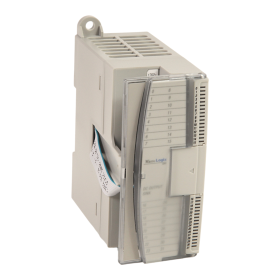
Page 7: Module Description
MicroLogix 1762-IQ32T DC Input Module Module Description 44910 44911 Left side view Front view This equipment is sensitive to electrostatic discharge (ESD). Follow ESD prevention guidelines when handling this equipment. Description Description Upper panel mounting tab Bus connector cover Lower panel mounting tab... -
Page 8: Mount The Module
Additional grounding connections from the power supply's mounting tabs or DIN rail (if used) are not required unless the mounting surface cannot be grounded. Refer to Industrial Automation Wiring and Grounding Guidelines, Allen-Bradley publication 1770-4.1, for additional information. Mounting Dimensions 90 mm (3.5 in.) - Page 9 Before mounting the module on a DIN rail, close the DIN rail latch. Press the DIN rail mounting area of the module against the DIN rail. The latch will momentarily open and lock into place. Use DIN rail end anchors (Allen-Bradley part number 1492-EA35 or 1492-EAH35) for vibration or shock environments. End anchor...
- Page 10 MicroLogix 1762-IQ32T DC Input Module Panel Mounting Use the dimensional template shown below to mount the module. The preferred mounting method is to use two M4 (#8) panhead screws per module. M3.5 (#6) panhead screws may also be used, but a washer may be needed to ensure a good mechanical contact. Mounting screws are required on every module.
-
Page 11: Field Wiring Connections
MicroLogix 1762-IQ32T DC Input Module Field Wiring Connections Grounding the Module In solid-state control systems, grounding and wire routing helps limit the effects of noise due to electromagnetic interference (EMI). Run the ground connection from the ground screw of the controller to the ground bus prior to connecting any devices. - Page 12 MicroLogix 1762-IQ32T DC Input Module Input Wiring Basic wiring of input devices to the 1762-IQ32T is shown below. Basic Input Wiring to the 1762-IQ32T Module 44920 Simplified Input Circuit Diagram ASIC Signal 44923 A write-on label is provided with the module. Mark the identification of each terminal with permanent ink, and slide the label back into the door.
-
Page 13: Wiring Options For The I/O Module
MicroLogix 1762-IQ32T DC Input Module Wiring Options for the I/O Module Included with your 32-point input module is a keyed 40-pin female connector and crimp type pins. These components allow you to wire I/O devices to the module using a 40-conductor cable or individual wires. -
Page 14: Labeling For The 1492 Interface Module
MicroLogix 1762-IQ32T DC Input Module Labeling for the 1492 Interface Module Several different stick-on label sets are provided on a single card with 1492 Interface Modules. Each label set is identified with an I/O module catalog number and words upper and lower to identify which terminal strip the label should be affixed to. -
Page 15: Assemble The Wire Contacts
MicroLogix 1762-IQ32T DC Input Module Assemble the Wire Contacts 1. Strip the wire insulation to expose 4 mm (5/32 in.) of wire. Crimp pins can accept 22...26 AWG wire. ATTENTION Be careful when stripping wires. Wire fragments that fall into the module could cause damage. - Page 16 MicroLogix 1762-IQ32T DC Input Module I/O Memory Mapping For each input module, slot x, words 0...1 in the input data file contain the current state of the field input points. Input Data File Bit Position Word Where: r = read 1762 Expansion I/O Addressing The addressing scheme for 1762 Expansion I/O is represented in the following figure.
-
Page 17: Specifications
MicroLogix 1762-IQ32T DC Input Module Specifications General Specifications Attribute Value Number of inputs Dimensions 90 x 40.4 x 87 mm HxWxD (3.54 x 1.59 x 3.43 in.) Shipping weight, approx. 200 g (7.05 oz) Bus current draw, max 170 mA @ 5V DC... - Page 18 MicroLogix 1762-IQ32T DC Input Module Input Specifications Attribute Value Off-state voltage, max 5 V DC Off-state current, max 1.0 mA On-state current, min 1.6 mA @ 10V DC 2 mA @ 15V DC On-state current, max 5.7 mA @ 26.4V DC 6.5 mA @ 30.0V DC...
- Page 19 MicroLogix 1762-IQ32T DC Input Module Environmental Specifications Attribute Value EFT/B immunity IEC 61000-4-4: ±2 kV at 5 kHz on signal ports Surge transient immunity IEC 61000-4-5: ±1 kV line-line(DM) and ±2 kV line-earth(CM) on signal ports Conducted RF immunity IEC 61000-4-6: 10V rms with 1 kHz sine-wave 80% AM from 150 kHz...80 MHz...
- Page 20 RA-DU002, available at http://www.rockwellautomation.com/literature/. Allen-Bradley, Rockwell Automation, MicroLogix, and TechConnect are trademarks of Rockwell Automation, Inc. Trademarks not belonging to Rockwell Automation are property of their respective companies. Publication 1762-IN019B-EN-P - June 2013 Supersedes Publication 1762-IN019A-EN-P - August 2009 Copyright ©...
Need help?
Do you have a question about the MicroLogix 1762-IQ32T and is the answer not in the manual?
Questions and answers