Sign In
Upload
Download
Table of Contents
Contents
Add to my manuals
Delete from my manuals
Share
URL of this page:
HTML Link:
Bookmark this page
Add
Manual will be automatically added to "My Manuals"
Print this page
×
Bookmark added
×
Added to my manuals
Manuals
Brands
Allen-Bradley Manuals
I/O Systems
1762-IR4
User manual
Allen-Bradley 1762-IR4 User Manual
Rtd/resistance input module
Hide thumbs
1
2
Table Of Contents
3
4
5
6
7
8
9
10
11
12
13
14
15
16
17
18
19
20
21
22
23
24
25
26
27
28
29
30
31
32
33
34
35
36
37
38
39
40
41
42
43
44
45
46
47
48
49
50
51
52
53
54
55
56
57
58
59
60
61
62
63
64
65
66
67
68
69
70
71
72
73
74
75
76
77
78
79
80
81
82
83
84
85
86
87
88
89
90
91
92
93
94
95
96
97
98
99
100
101
102
103
104
page
of
104
Go
/
104
Contents
Table of Contents
Troubleshooting
Bookmarks
Table of Contents
Table of Contents
How to Use this Manual
Manual Contents
Related Documentation
Preface
Who Should Use this Manual
Conventions Used in this Manual
Rockwell Automation Support
Your Questions or Comments on the Manual
Chapter 1 General Description
Overview
RTD Compatibility
Resistance Device Compatibility
Hardware Features
General Diagnostic Features
System Overview
System Operation
Module Operation
Module Field Calibration
Chapter 2 Compliance to European Union Directives
EMC Directive
Low Voltage Directive
Installation and Wiring
General Considerations
Hazardous Location Considerations
Prevent Electrostatic Discharge
Remove Power
Selecting a Location
Power Requirements
Mounting
Minimum Spacing
DIN Rail Mounting
Panel Mounting
System Assembly
Field Wiring Connections
System Wiring Guidelines
RTD Wiring Considerations
Wiring the Finger-Safe Terminal Block
Wire Size and Terminal Screw Torque
Wiring Input Devices to the Module
Wiring Rtds
Wiring Resistance Devices (Potentiometers)
Chapter 3 Module Memory Map
Input Image
Configuration File
Module Data, Status, and Channel Configuration
Accessing Input Image File Data
Input Data File
Input Data Values
General Status Flag Bits (S0 to S3)
Open-Circuit Flag Bits (OC0 to OC3)
Over-Range Flag Bits (O0 to O3)
Under-Range Flag Bits (U0 to U3)
Configuring Channels
Configuration Data File
Channel Configuration
Enabling or Disabling a Channel (Bit 15)
Selecting Data Format (Bits 12 to 14)
Selecting Input/Sensor Type (Bits 8 to 11)
Selecting Temperature Units/Mode (Bit 7)
Selecting Open-Circuit Response (Bits 5 and 6)
Selecting Cyclic Lead Compensation (Bit 4)
Selecting Excitation Current (Bit 3)
Setting Filter Frequency (Bits 0 to 2)
Selecting Enable/Disable Cyclic Autocalibration (Word 4, Bit 0)
Determining Effective Resolution and Range
Determining Module Update Time
Effects of Autocalibration on Module Update Time
Enabled
Effects of Cyclic Lead Wire Compensation on Module Update Time
Calculating Module Update Time with Cyclic Lead Wire Compensation Enabled
Impact of Autocalibration and Lead Wire Compensation on Module Startup
Effects of Autocalibration on Accuracy
Chapter 4 Safety Considerations
Indicator Lights
Activating Devices When Troubleshooting
Stand Clear of the Equipment
Program Alteration
Safety Circuits
Diagnostics and Troubleshooting
Module Operation Vs. Channel Operation
Channel Diagnostics
Invalid Channel Configuration Detection
Out-Of-Range Detection
Open-Wire or Short-Circuit Detection
Power-Up Diagnostics
Non-Critical Vs. Critical Module Errors
Module Error Definition Table
Module Error Field
Extended Error Information Field
Error Codes
Contacting Rockwell Automation
Module Inhibit Function
Appendix A
General Specifications
Input Specifications
Cable Specifications
RTD Standards
1762-IR4 Configuration File
Appendix B
Module Addressing
Configuration Using Rslogix 500 Version 5.50 or Higher
Configuration Using Rslogix 500 Version 5.2 or Lower
Advertisement
Quick Links
1
Rtd Compatibility
2
Installation and Wiring
3
Field Wiring Connections
Download this manual
See also:
Reference Manual
,
User Manual
MicroLogix™ 1200
RTD/Resistance
Input Module
(Catalog Number 1762-IR4)
User Manual
Table of
Contents
Previous
Page
Next
Page
1
2
3
4
5
Advertisement
Table of Contents
Troubleshooting
Diagnostics and Troubleshooting
69
Activating Devices When Troubleshooting
70
Need help?
Do you have a question about the 1762-IR4 and is the answer not in the manual?
Ask a question
Questions and answers
Related Manuals for Allen-Bradley 1762-IR4
I/O Systems Allen-Bradley 1756 ControlLogix User Manual
Controlnet network configuration (103 pages)
I/O Systems Allen-Bradley 1769-IQ32 Installation Instructions Manual
Compact 32-point 24v dc sink/source input module (16 pages)
I/O Systems Allen-Bradley 1769-ECL Installation Instructions Manual
Compact i/o end caps/terminators (10 pages)
I/O Systems Allen-Bradley 1769-ECR Installation Instructions Manual
Compact i/o end caps/terminators (10 pages)
I/O Systems Allen-Bradley Compact 1769-IF4 Installation Instructions Manual
Analog input module (24 pages)
I/O Systems Allen-Bradley Compact 1769-IR6 User Manual
I/o rtd/resistance input module (116 pages)
I/O Systems Allen-Bradley MicroLogix 1762-IF2OF2 Installation Instructions Manual
Analog input/output module (24 pages)
I/O Systems Allen-Bradley MicroLogix 1762-IQ32T Installation Instructions Manual
Dc input module (20 pages)
I/O Systems Allen-Bradley 1762-IQ8OW6 Installation Instructions Manual
Dc-input/relay-output combination module (20 pages)
I/O Systems Allen-Bradley 1769-HSC Installation Instructions Manual
Compact i/o high-speed counter module (32 pages)
I/O Systems Allen-Bradley 1769-IT6 User Manual
Compact i/o thermocouple/mv input module (20 pages)
I/O Systems Allen-Bradley B Series Installation Instructions Manual
Flex i/o remote i/o adapter (12 pages)
I/O Systems Allen-Bradley 1746 Series Installation Instructions Manual
Discrete i/o modules, combination input/output module (56 pages)
I/O Systems Allen-Bradley POINT I/O User Manual
2 port ethernet/ip adapters (118 pages)
I/O Systems Allen-Bradley ControlLogix User Manual
Controllogix data highway plus/remote i/o communication interface module (165 pages)
I/O Systems Allen-Bradley 1771-ASB User Manual
Remote i/o adapter module (72 pages)
Summarization of Contents
Preface
Who Should Use This Manual
Identifies the target audience responsible for control systems using the module.
Rockwell Automation Support
Provides contact information for technical assistance and support.
Chapter 1: Overview
General Description
Provides a general overview of the 1762-IR4 module's capabilities.
RTD Compatibility
Details the types of RTDs compatible with the module and their specifications.
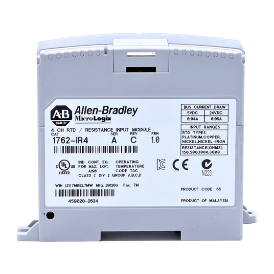
Hardware Features
Illustrates and describes the physical components of the RTD/resistance module.
Module Field Calibration
Details the module's autocalibration process for accuracy.
Chapter 2: Installation and Wiring
Power Requirements
Details the module's power consumption and supply needs.
Hazardous Location Considerations
Specifies suitability for Class I, Division 2 locations and associated warnings.
Prevent Electrostatic Discharge
Safety guidelines to prevent ESD damage to modules.
RTD Wiring Considerations
Guidance on selecting cables and wiring RTDs for accuracy.
Chapter 3: Module Data, Status, and Channel Configuration
Input Data File
Details the data structure for reading input values and status.
Configuring Channels
Outlines the process of setting channel operation details like type and units.
Selecting Data Format (Bits 12 to 14)
Explains options for input data formats like raw, engineering units, etc.
Determining Module Update Time
Explains how module update time is calculated based on channels and filters.
Effects of Autocalibration on Accuracy
Shows how autocalibration affects the module's measurement accuracy.
Chapter 4: Diagnostics and Troubleshooting
Safety Considerations
Emphasizes safety precautions during troubleshooting procedures.
Error Codes
Lists and explains various module error codes and their meanings.
Contacting Rockwell Automation
Lists information needed when contacting support for assistance.
Appendix B: Configuring the 1762-IR4 Module Using RSLogix 500
Module Addressing
Explains the addressing scheme for the module's input image.
Configuration Using RSLogix 500 Version 5.50 or Higher
Guides through module configuration using RSLogix 500 v5.50 and later.
Glossary
filter frequency
Defines the selectable frequency for a digital filter.
module update time
Defines time to sample, convert, and provide data to processor.
resolution
Defines the smallest detectable change in a measurement.
Table of Contents
Print
Rename the bookmark
Delete bookmark?
Delete from my manuals?
Login
Sign In
OR
Sign in with Facebook
Sign in with Google
Upload manual
Upload from disk
Upload from URL
Need help?
Do you have a question about the 1762-IR4 and is the answer not in the manual?
Questions and answers