Table of Contents
Advertisement
Installation Instructions
Compact I/O High-speed Counter
Module
Catalog Number 1769-HSC
Topic
About the Module
The 1769-HSC module has six differential DC inputs that can be used as two to four high-speed
counters. The module has 4 sourcing DC outputs and 12 additional 'virtual' outputs. The
counters provide accumulated pulse counts to the input array of the module and can cause
onboard outputs to react to input conditions at high speed.
The module is compatible with CompactLogix controllers, MicroLogix 1500 controllers , and
the 1769-ADN DeviceNet adapter.
Page
2
3
4
5
6
7
8
8
10
12
13
20
22
23
26
30
Advertisement
Table of Contents

Related Manuals for Allen-Bradley 1769-HSC


Summary of Contents for Allen-Bradley 1769-HSC
-
Page 1: Table Of Contents
Additional Resources About the Module The 1769-HSC module has six differential DC inputs that can be used as two to four high-speed counters. The module has 4 sourcing DC outputs and 12 additional ‘virtual’ outputs. The counters provide accumulated pulse counts to the input array of the module and can cause onboard outputs to react to input conditions at high speed. -
Page 2: Important User Information
Compact I/O High-speed Counter Module Important User Information Solid-state equipment has operational characteristics differing from those of electromechanical equipment. Safety Guidelines for the Application, Installation and Maintenance of Solid State Controls (Publication SGI-1.1 available from your local Rockwell Automation sales office or online at http://www.rockwellautomation.com/literature/) describes some important differences between solid-state equipment and hard-wired electromechanical devices. -
Page 3: Environment And Enclosure
Compact I/O High-speed Counter Module Environment and Enclosure ATTENTION: This equipment is intended for use in a Pollution Degree 2 industrial environment, in overvoltage Category II applications (as defined in IEC publication 60664-1), at altitudes up to 2000 m (6562 ft) without derating. This equipment is considered Group 1, Class A industrial equipment according to IEC/CISPR 11. -
Page 4: North American Hazardous Location Approval
Compact I/O High-speed Counter Module North American Hazardous Location Approval The following information applies when operating Informations sur l’utilisation de cet équipement en this equipment in hazardous locations. environnements dangereux. Products marked "CL I, DIV 2, GP A, B, C, D" are suitable for Les produits marqués "CL I, DIV 2, GP A, B, C, D"... -
Page 5: Module Features
(with or without direction), or similar products used to monitor counting, flow, or frequency. The input voltage range is 2.6…30V DC. The 1769-HSC module includes all of the standard 1769 I/O module features, such as rackless, removable terminal block, integrated high-speed bus/backplane, panel, or DIN rail mounting. -
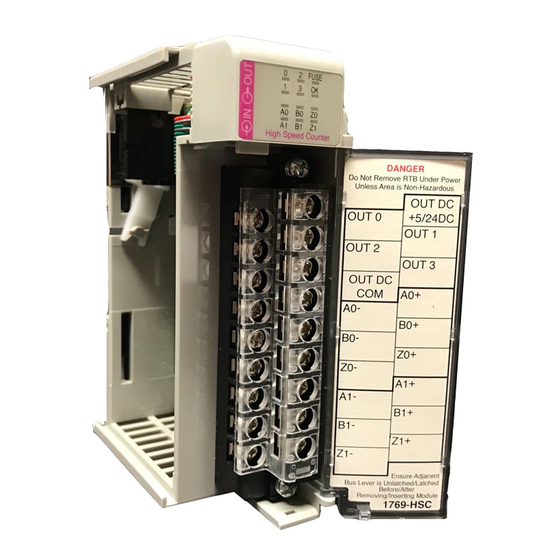
Page 6: Hardware Description
OUT 1 OUT 2 OUT 3 OUT DC Ensure Adjacent Bus Lever is Unlatched/Latched Before/After Removing/Inserting Module 1769-HSC 45196 Item Description Bus lever Upper-panel mounting tab Lower-panel mounting tab Module status indicators (6 Input, 4 Output, 1 Fuse, 1 OK) -
Page 7: Module Installation
Compact I/O High-speed Counter Module Module Installation The 1769-HSC module is suitable for use in an industrial environment when installed in accordance with these instructions. Specifically, this equipment is intended for use in clean, dry environments (Pollution Degree 2 ) and with circuits not exceeding Over Voltage Category II (IEC 60664-1). -
Page 8: System Planning
Compact I/O High-speed Counter Module System Planning There are several factors to consider when planning your system: • A 1769-ECR (right-end cap) or 1769-ECL (left-end cap) is required to terminate the end of the Compact I/O bus. • Each bank of Compact I/O modules must have its own power supply. (A MicroLogix 1500 base unit acts as the power supply for modules directly connected to it.) •... - Page 9 Compact I/O High-speed Counter Module Refer to the illustration when assembling the Compact I/O system. See page 6 for a description of the module. 45197 1. Disconnect the power. 2. Check that the bus lever of the module (A) is in the unlocked (fully right) position. 3.
-
Page 10: System Mounting
Compact I/O High-speed Counter Module System Mounting ATTENTION: This product is intended to be mounted to a well-grounded mounting surface, such as a metal panel. Additional grounding connections from the power supply's mounting tabs or DIN rail (if used) are not required unless the mounting surface cannot be grounded. - Page 11 Compact I/O High-speed Counter Module Figure 2 - Compact I/O Modules with MicroLogix 1500 Base Unit and Processor 35 mm 168 mm Mounting Hole 28.5 mm (6.62 in.) (1.38 in.) Dimension (1.12 in.) 35 mm 147 mm (5.79 in.) (1.38 in.) 13.5 mm 14.7 mm DIN Rail Center Line...
-
Page 12: Replace The Module Within A System
Compact I/O High-speed Counter Module DIN Rail Mounting The module can be mounted on the following DIN rails: • EN 50 022 - 35 x 7.5 mm (1.38 x 0.3 in.) • EN 50 022 - 35 x 15 mm (1.38 x 0.59 in.) ATTENTION: During panel or DIN-rail mounting of all devices, be sure that all debris (metal chips, wire strands, and so forth) is kept from falling into the module. -
Page 13: Field Wiring Connections
Compact I/O High-speed Counter Module If you feel excessive resistance, make sure that you disconnected the module from the bus and that you removed both mounting screws (or opened the DIN latches). It may be necessary to rock the module slightly from front to back to remove it, or, in a panel-mounted system, to loosen the screws of adjacent modules. - Page 14 • Keep shield connection to ground as short as possible. • Ground the shield drain wire at the 1769-HSC module’s input end only. Refer to the Industrial Automation Wiring and Grounding Guidelines, publication 1770-4.1, for additional installation requirements Terminal Block Guidelines •...
- Page 15 Compact I/O High-speed Counter Module Figure 5 - Single-Ended Encoder Wiring Cable Power +VDC Supply A1(+) A1(–) B1(+) Allen-Bradley B1(–) 845H Series Z1(+) Single-ended Z1(–) Encoder Shield Shield/Housing Earth Connect only if housing is electronically Module Inputs isolated from the motor and ground.
- Page 16 Compact I/O High-speed Counter Module Figure 6 - Discrete Device Wiring +VDC Power Supply Proximity Sensor A1(+) A1(–) Solid-state B1(+) Switch B1(–) Z1(+) Z1(–) Photo-electric Sensor with Open Collector Sinking Output Module Inputs External resistors are required if they are not internal to the sensor. The pull-up resistor (R) value depends on the power supply value.
- Page 17 Compact I/O High-speed Counter Module Output Wiring Basic wiring of output devices to the module is shown in Figure 7. ATTENTION: Follow these guidelines: • Miswiring of the module to an AC power source or applying reverse polarity will damage the module. •...
- Page 18 Compact I/O High-speed Counter Module Wire the Finger-safe Terminal Block When wiring the terminal block, keep the finger-safe cover in place. Wiring the Finger-safe Terminal Block Upper Retaining Screw Lower Retaining Screw 1. Loosen the terminal screws to be wired. 2.
- Page 19 ATTENTION: Be careful when stripping wires. Wire fragments that fall into a module could cause damage at powerup. 3. At the 1769-HSC module’s input end of the cable, twist the drain wire and foil shield together, bending them away from the cable, and apply shrink wrap, grounding the shield at this end by using as short a lead-length as possible.
-
Page 20: Output Operation
Under-voltage Condition If the field supply voltage falls below a value of approximately 4V DC, all of the 1769-HSC module’s outputs shut down and remain off until the field supply voltage returns to a value within the module’s normal operating range. - Page 21 Compact I/O High-speed Counter Module Transistor Output Transient Pulses The maximum duration of the transient pulse occurs when minimum load is connected to the output. However, for most applications, the energy of the transient pulse is not sufficient to energize the load. ATTENTION: A transient pulse occurs in transistor outputs when the external DC supply voltage is applied to the output common terminals (for example, via the master control relay).
-
Page 22: Module Powerup
Compact I/O High-speed Counter Module Module Powerup At module powerup, a series of internal diagnostic tests are FUSE performed. These diagnostic tests must be successfully completed or the module OK status indicator remains off or red, and a module error is reported to the controller. Diagnostic Indicators Status Color... -
Page 23: Temperature Derating
Compact I/O High-speed Counter Module Temperature Derating The following graphs indicate how much current can be drawn from the power supply at the indicated case temperature without damaging it. Maximum Input Voltage - 24V DC Operation Voltage Derating Based on Temperature 26.4V DC at 55 °C (131 °F) (-32) - Page 24 Compact I/O High-speed Counter Module Maximum Output Current per Point - 5V DC Operation Current Derating Based on Temperature 0.5 A at 60 °C (140 °F) (68) (158) (-32) (50) (86) (104) (122) (140) Ambient Temperature, °C (°F) 45206 Temperature Derated Current 0…40 °C (-32…104 °F) 60 °C (140 °F)
- Page 25 Compact I/O High-speed Counter Module Maximum Output Current per Point - 24V DC Operation Current Derating Based on Temperature 0.25 A at 60 °C (140 °F) (158) (-32) (50) (68) (86) (104) (122) (140) Ambient Temperature, °C (°F) 45208 Temperature Derated Current 0…40 °C (-32…104 °F) 55 °C (131°F)
-
Page 26: Specifications
Compact I/O High-speed Counter Module Specifications Technical Specifications - 1769-HSC Attribute 1769-HSC Dimensions (H x W x D), approx. 118 x 35 x 87 mm (4.65 x 1.38 x 3.43 in.) Height including mounting tabs is 138 mm (5.43 in.) Shipping weight (with carton), approx. - Page 27 Compact I/O High-speed Counter Module Input Specifications - 1769-HSC Attribute 1769-HSC On-state voltage, min 2.6V DC On-state current, min 6.8 mA Off-state voltage, max 1.0V DC Off-state current, max 1.5 mA Off-state leakage current, max 1.5 mA Input current, max...
- Page 28 Compact I/O High-speed Counter Module Environmental Specifications - 1769-HSC Attribute 1769-HSC Temperature, operating 0…60 °C (32…140 °F) IEC 60068-2-1 (Test Ad, Operating Cold), IEC 60068-2-2 (Test Bd, Operating Dry Heat), IEC 60068-2-14 (Test Nb, Operating Thermal Shock) Temperature, surrounding air, max 40 °C (104 °F)
- Page 29 Compact I/O High-speed Counter Module Environmental Specifications - 1769-HSC Attribute 1769-HSC EFT/B immunity ±2 kV at 5 kHz on power ports ±2 kV at 5 kHz on signal ports IEC 61000-4-4 Surge transient immunity ±1 kV line-line (DM) and ±2 kV line-earth (CM) on power ports ±1 kV line-line (DM) and ±2 kV line-earth (CM)
-
Page 30: Additional Resources
Compact I/O High-speed Counter Module Additional Resources These documents contain additional information concerning related Rockwell Automation products. Resource Description Compact High-speed Counter Module User Detailed description of how to use your High-speed Manual, publication 1769-UM006 Counter Module. ControlLogix System User Manual, Detailed description of how to use your ControlLogix publication 1756-UM001... - Page 31 Compact I/O High-speed Counter Module Notes: Publication 1769-IN030B-EN-P - October 2010...
- Page 32 RA-DU002, available at http://www.rockwellautomation.com/literature/. Allen-Bradley, Rockwell Software, Rockwell Automation, CompactLogix, MicroLogix, Compact I/O, ControlLogix, and TechConnect are trademarks of Rockwell Automation, Inc. Trademarks not belonging to Rockwell Automation are property of their respective companies.
Need help?
Do you have a question about the 1769-HSC and is the answer not in the manual?
Questions and answers