
Related Manuals for Allen-Bradley 1762-IQ8OW6


Summary of Contents for Allen-Bradley 1762-IQ8OW6
-
Page 1: Table Of Contents
Installation Instructions DC-Input/Relay-Output Combination Module Catalog Number 1762-IQ8OW6 Table of Contents See Page Important User Information Overview North American Hazardous Location Approval Module Description Install the DC-Input/Relay-Output Combination Module Mount the Module on a DIN Rail Mount the Module on a Panel... -
Page 2: Important User Information
DC-Input/Relay-Output Combination Module Important User Information Solid state equipment has operational characteristics differing from those of electromechanical equipment. Safety Guidelines for the Application, Installation and Maintenance of Solid State Controls (Publication SGI-1.1 available from your local Rockwell Automation sales office or online at http://literature.rockwellautomation.com) describes some important differences between solid state equipment and hard-wired electromechanical devices. -
Page 3: Overview
DC-Input/Relay-Output Combination Module Overview The 1762 I/O is suitable for use in an industrial environment when installed in accordance with these instructions. Specifically, this equipment is intended for use in clean, dry environments (Pollution degree 2 ) and to circuits not exceeding Over Voltage Category II (IEC 60664-1). -
Page 4: North American Hazardous Location Approval
DC-Input/Relay-Output Combination Module North American Hazardous Location Approval The following modules are North American Hazardous Location approved: 1762-IQ8OW6 The following information applies when Informations sur l’utilisation de cet operating this equipment in hazardous équipement en environnements dangereux: locations: Products marked "CL I, DIV 2, GP A, B, C, D" are Les produits marqués "CL I, DIV 2, GP A, B, C, D"... -
Page 5: Module Description
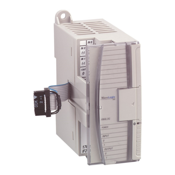
DC-Input/Relay-Output Combination Module Module Description Item Description Item Description upper panel mounting tab bus connector cover lower panel mounting tab flat ribbon cable with bus connector (female pins) I/O diagnostic LEDs terminal block module door with terminal identification label 8 DIN rail latch bus connector with male pins pull loop... -
Page 6: Install The Dc-Input/Relay-Output Combination Module
Before mounting the module on a DIN-rail, close the DIN-rail latch. Press the DIN-rail mounting area of the module against the DIN-rail. The latch will momentarily open and lock into place. Use DIN-rail end anchors (Allen-Bradley part number 1492-EA35 or 1492-EAH35) for vibration or shock environments. Publication 1762-IN018B-EN-P - July 2013... -
Page 7: Mount The Module On A Panel
DC-Input/Relay-Output Combination Module End Anchor End Anchor For environments with greater vibration and shock concerns, use the panel mounting method described below, instead of DIN-rail mounting. Mount the Module on a Panel Use the dimensional template shown below to mount the module. The preferred mounting method is to use two M4 or #8 panhead screws per module. -
Page 8: Wire The Dc-Input/Relay-Output Combination Module
Field devices connected to the positive side (+V) of the field supply are sourcing field devices. Surge Suppression – Connecting surge suppressors across your external inductive load will extend the life of the relay contacts. For additional details, refer to Industrial Automation Wiring and Grounding Guidelines, Allen-Bradley publication 1770-4.1. -
Page 9: Ground The Dc-Input/Relay-Output Combination Module
This product is intended to be mounted to a well-grounded mounting surface such as a metal panel. Additional grounding connections from the module’s mounting tabs or DIN rail (if used) are not required unless the mounting surface cannot be grounded. Refer to Industrial Automation Wiring and Grounding Guidelines, Allen-Bradley publication , for 1770-4.1 additional information. -
Page 10: System Assembly
DC-Input/Relay-Output Combination Module If you need to remove the finger-safe cover, insert a screw driver into one of the square wiring holes and gently pry the cover off. If you wire the terminal block with the finger-safe cover removed, you will not be able to put it back on the terminal block because the wires will be in the way. -
Page 11: Input Memory Map
DC-Input/Relay-Output Combination Module EXPLOSION HAZARD ATTENTION • In Class I, Division 2 applications, the bus connector must be fully seated and the bus connector cover must be snapped in place. • In Class I, Division 2 applications, all modules must be mounted in direct contact with each other as shown on page 6. -
Page 12: Output Memory Map
DC-Input/Relay-Output Combination Module Output Memory Map For each output module, the output data file contains the controller-directed state of the digital output points. Bit positions 0…15 correspond to output terminals 0…15. Bit Position w = write only, w* = user can write but outputs not available, 0= always at 0 or OFF state The output addressing scheme for 1762 expansion I/O is shown below. -
Page 13: Specifications
DC-Input/Relay-Output Combination Module Specifications Input Specifications Specification Value Voltage Category 24V DC (Sink/Source) Operating Voltage Range 10…30V DC @ 30 °C (86 °F) 10…26.4V DC @ 65 °C (149 °F) Number of Inputs On-state Voltage, (Min) 10V DC Off-state Voltage, (Max) 5V DC On-state Current, (Min) 2.0 mA... - Page 14 DC-Input/Relay-Output Combination Module Output Specifications Specification Value Voltage Range 5…265V AC 5…125V DC Commons per Module Output Type 6-Form A (normally open) Signal Delay Time On-delay: 10 mS (max) Off-delay: 10 mS (max) Off Leakage Current 0 mA On-state Current (Min.) 10 mA @ 5V DC Continuous Current per Point See table on page 14.
- Page 15 DC-Input/Relay-Output Combination Module General Specifications Specification Value Dimensions, HxWxD 90 x 40.4 x 87 (3.54 x 1.59 x 3.43 in.) height including mounting tabs is 110 mm (4.33in.) Approximate Shipping Weight 280g (0.62 lbs.) (with carton) Bus Current Draw, (Max) 110 mA @ 5V DC 80 mA @ 24V DC Heat Dissipation...
- Page 16 DC-Input/Relay-Output Combination Module Environmental Specifications Specification Value Operation Temperature Range -20…+65 °C (-4…+149 °F) Storage Temperature Range -40…+85 °C (-40…+185 °F) Operating Humidity 5…95% non-condensing Operating Altitude 2000 m (6561 ft) Certifications Certification (when Value product is marked) c-UL-us UL Listed Industrial Control Equipment, certified for US and Canada. UL Listed for Class I, Division 2 Group A,B,C,D Hazardous Locations, certified for U.S.
-
Page 17: Additional Resources
Guidelines, publication 1770-4.1. techniques. If you would like a manual, you can: • download a free electronic version from the internet: http://literature.rockwellautomation.com. • purchase a printed manual by contacting your local Allen-Bradley distributor or Rockwell Automation representative Publication 1762-IN018B-EN-P - July 2013... - Page 18 DC-Input/Relay-Output Combination Module Notes: Publication 1762-IN018B-EN-P - July 2013...
- Page 19 DC-Input/Relay-Output Combination Module Notes: Publication 1762-IN018B-EN-P - July 2013...
- Page 20 RA-DU002, available at http://www.rockwellautomation.com/literature/. Allen-Bradley, Rockwell Automation, MicroLogix, and TechConnect are trademarks of Rockwell Automation, Inc. Trademarks not belonging to Rockwell Automation are property of their respective companies. Publication 1762-IN018B-EN-P - July 2013 Supersedes Publication 1762-IN018A-EN-P - November 2005 Copyright ©...
Need help?
Do you have a question about the 1762-IQ8OW6 and is the answer not in the manual?
Questions and answers