Advertisement
Table of Contents
- 1 Table of Contents
- 2 Important User Information
- 3 Module Description
- 4 Module Installation
- 5 System Assembly
- 6 Mounting Expansion I/O
- 7 Replacing a Single Module Within a System
- 8 Field Wiring Connections
- 9 I/O Memory Mapping
- 10 Spare/Replacement Module Parts
- 11 Specifications
- 12 Hazardous Location Considerations
- 13 For more Information
- Download this manual
Compact 32-point 24V dc Sink/Source
Input Module
Catalog Number 1769-IQ32
Use this document as a guide when installing a Compact™ 32-point 24V dc sink/source
input module.
Topic
Installation Instructions
Page
2
3
4
5
6
8
9
12
12
13
15
16
Publication 1769-IN032A-EN-P - April 2003
Advertisement
Table of Contents

Related Manuals for Allen-Bradley 1769-IQ32


Summary of Contents for Allen-Bradley 1769-IQ32
-
Page 1: Table Of Contents
Installation Instructions Compact 32-point 24V dc Sink/Source Input Module Catalog Number 1769-IQ32 Use this document as a guide when installing a Compact™ 32-point 24V dc sink/source input module. Topic Page Important User Information Module Description Module Installation System Assembly Mounting Expansion I/O... -
Page 2: Important User Information
Rockwell Automation does not assume responsibility or liability (to include intellectual property liability) for actual use based upon the examples shown in this publication. Allen-Bradley publication SGI-1.1, Safety Guidelines for the Application, Installation and Maintenance of Solid-State Control (available from your local Rockwell Automation office), describes some important differences between solid-state equipment and electromechanical devices that should be taken into consideration when applying products such as those described in this publication. -
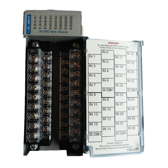
Page 3: Module Description
IN 29 IN 12 IN 28 IN 15 IN 31 identification label IN 14 IN 30 DC COM DC COM 1769-IQ32 movable bus connector with female pins stationary bus connector with male pins nameplate label upper tongue-and-groove slots lower tongue-and-groove slots... -
Page 4: Module Installation
Compact 32-point 24V dc Sink/Source Input Module Module Installation Compact I/O is suitable for use in an industrial environment when installed in accordance with these instructions. Specifically, this equipment is intended for use in clean, dry environments (Pollution degree 2 ) and to circuits not exceeding Over Voltage Category II (IEC 60664-1). -
Page 5: System Assembly
Compact 32-point 24V dc Sink/Source Input Module System Assembly The module can be attached to the controller or an adjacent I/O module before or after mounting. For mounting instructions, see Panel Mounting on page 6, or DIN Rail Mounting on page 8. To work with a system that is already mounted, see Replacing a Single Module within a System on page 8. -
Page 6: Mounting Expansion I/O
Compact 32-point 24V dc Sink/Source Input Module 7. Attach an end cap terminator (5) to the last module in the system by using the tongue-and-groove slots as before. 8. Lock the end cap bus terminator (6). A 1769-ECR or 1769-ECL right or left end cap must be used to IMPORTANT terminate the end of the serial communication bus. - Page 7 Compact 32-point 24V dc Sink/Source Input Module Panel Mounting Using the Dimensional Template Spacing for single-wide modules 35mm (1.378 in.) Spacing for one-and-a half-wide modules 52.5mm (2.067 in.) Refer to host controller documentation for this dimension. Note: Overall hole spacing tolerance: ±0.4mm (0.016 in.).
-
Page 8: Replacing A Single Module Within A System
Compact 32-point 24V dc Sink/Source Input Module NOTE: If mounting more modules, mount only the last one of this group and put the others aside. This reduces remounting time during drilling and tapping of the next group. 7. Repeat steps 1 to 6 for any remaining modules. DIN Rail Mounting The module can be mounted using these DIN rails: 35 x 7.5 mm (EN 50 022 - 35 x 7.5) or 35 x 15 mm (EN 50 022 - 35 x 15). -
Page 9: Field Wiring Connections
Refer to Industrial Automation Wiring and Grounding Guidelines, Allen-Bradley publication 1770-4.1, for additional information. Input Wiring Basic wiring of input devices to the 1769-IQ32 is shown below. – Miswiring of the module to an AC power source will damage ATTENTION the module. - Page 10 Compact 32-point 24V dc Sink/Source Input Module 1769-IQ32 +DC (Sinking) – DC (Sourcing) IN 0 IN 1 IN 2 24Vdc IN 3 IN 4 IN 5 IN 6 IN 7 COM 1 – DC (Sinking) + DC (Sourcing) + DC (Sinking) –...
- Page 11 Compact 32-point 24V dc Sink/Source Input Module Removing the Finger-safe Terminal Block When wiring field devices to the module, it is not necessary to remove the terminal block. If you remove the terminal block, use the write-on label on the side of the terminal block to identify the module slot lcation and type.
-
Page 12: I/O Memory Mapping
Compact 32-point 24V dc Sink/Source Input Module Wire Size and Terminal Screw Torque Each terminal accepts as many as two wires with these restrictions: Wire Type Wire Size Terminal Screw Retaining Screw Torque Torque Solid Cu-90°C (194°F) #14 to #22 AWG 0.68 Nm (6 in-lbs) 0.46 Nm (4.1 in-lbs) Stranded... -
Page 13: Specifications
Compact 32-point 24V dc Sink/Source Input Module Specifications General Specifications Specification Value Dimensions 118 mm (height) x 87 mm (depth) x 52.5 mm (width) height including mounting tabs is 138 mm 4.65 in. (height) x 3.43 in (depth) x 2.07 in (width) height including mounting tabs is 5.43 in. - Page 14 Compact 32-point 24V dc Sink/Source Input Module Input Specifications Specification 1769-IQ32 Voltage Category 24V dc (sink/source Operating Voltage Range 10 to 30V dc at 30°C (86°F) 10 to 26.4V dc at 60°C (140°F) Number of Inputs Bus Current Draw (max.) 170 mA at 5V dc (0.85W)
-
Page 15: Hazardous Location Considerations
Compact 32-point 24V dc Sink/Source Input Module Hazardous Location Considerations This equipment is suitable for use in Class I, Division 2, Groups A, B, C, D or non-hazardous locations only. The following WARNING statement applies to use in hazardous locations. EXPLOSION HAZARD WARNING •... -
Page 16: For More Information
For More Information Refer to this Document Pub. No. A more detailed description of how to install MicroLogix 1200 and MicroLogix 1764-RM001B-US-P and use your Compact I/O with MicroLogix 1500 Programmable Controllers User 1200 & 1500 programmable controller. Manual A more detailed description of how to install 1769-ADN DeviceNet Adapter User 1769-UM001A-US-P and use your Compact I/O with the...
Need help?
Do you have a question about the 1769-IQ32 and is the answer not in the manual?
Questions and answers