Advertisement
Table of Contents
- 1 Table of Contents
- 2 For more Information
- 3 Description
- 4 Installation
- 5 Mounting
- 6 System Assembly
- 7 Field Wiring Connections
- 8 Input Type Selection
- 9 Output Type Selection
- 10 Wiring
- 11 I/O Memory Mapping
- 12 Specifications
- 13 Hazardous Location Considerations
- 14 Environnements Dangereux
- Download this manual
Installation Instructions
MicroLogix™ Analog Input/Output
Module
(Catalog Number 1762-IF2OF2)
Inside...
For More Information................................................................................2
Description ................................................................................................3
Installation ................................................................................................4
Mounting...................................................................................................5
System Assembly......................................................................................7
Field Wiring Connections..........................................................................8
Input Type Selection ................................................................................ 8
Output Type Selection ............................................................................. 8
Wiring ..................................................................................................... 9
I/O Memory Mapping .............................................................................13
Specifications .........................................................................................18
Hazardous Location Considerations .......................................................22
Environnements dangereux ....................................................................23
Publication 1762-IN005A-US-P
Advertisement
Table of Contents

Subscribe to Our Youtube Channel
Related Manuals for Allen-Bradley MicroLogix 1762-IF2OF2


Summary of Contents for Allen-Bradley MicroLogix 1762-IF2OF2
-
Page 1: Table Of Contents
Installation Instructions MicroLogix™ Analog Input/Output Module (Catalog Number 1762-IF2OF2) Inside… For More Information................2 Description ....................3 Installation ....................4 Mounting....................5 System Assembly..................7 Field Wiring Connections................8 Input Type Selection ................8 Output Type Selection ................8 Wiring ..................... 9 I/O Memory Mapping ................13 Specifications ..................18 Hazardous Location Considerations ............22 Environnements dangereux ..............23... -
Page 2: For More Information
MicroLogix™ Analog Input/Output Module For More Information Refer to this Document Pub. No. Information on installing, wiring, and MicroLogix 1200 Programmable 1762-UM001A-US-P operating a MicroLogix 1200 Controllers User Manual Programmable Controller Installation guide for the MicroLogix MicroLogix 1200 Programmable 1762-IN006A-ML-P 1200 Programmable Controller. -
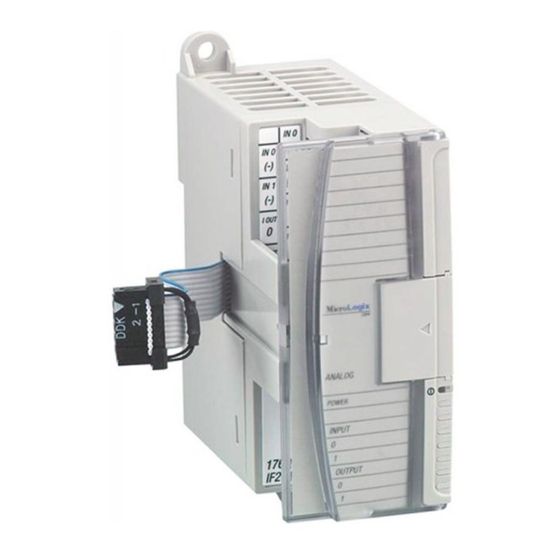
Page 3: Description
MicroLogix™ Analog Input/Output Module Description Item Description upper panel mounting tab lower panel mounting tab power diagnostic LED module door with terminal identification label bus connector with male pins bus connector cover flat ribbon cable with bus connector (female) terminal block DIN rail latch pull loop input type selector switch... -
Page 4: Installation
MicroLogix™ Analog Input/Output Module Installation 1762 I/O is suitable for use in an industrial environment when installed in accordance with these instructions. Specifically, this equipment is intended for use in clean, dry environments (Pollution degree 2 ) and to circuits not exceeding Over Voltage Category II (IEC 60664-1). -
Page 5: Mounting
MicroLogix™ Analog Input/Output Module Mounting Do not remove protective debris strip until after the module and ATTENTION all other equipment near the module is mounted and wiring is complete. Once wiring is complete and the module is free of debris, carefully remove protective debris strip. Failure to remove strip before operating can cause overheating. - Page 6 DIN rail mounting area of the module against the DIN rail. The latch will momentarily open and lock into place. Use DIN rail end anchors (Allen-Bradley part number 1492-EA35 or 1492-EAH35) for environments with vibration or shock concerns. End Anchor...
-
Page 7: System Assembly
MicroLogix™ Analog Input/Output Module System Assembly The expansion I/O module is attached to the controller or another I/O module by means of a ribbon cable after mounting as shown below. Use the pull loop on the connector to disconnect modules. Do NOTE not pull on the ribbon cable. -
Page 8: Field Wiring Connections
DIN rail (if used) are not required unless the mounting surface cannot be grounded. Refer to Industrial Automation Wiring and Grounding Guidelines, Allen-Bradley publication 1770-4.1, for additional information. Input Type Selection Select the input type, current or voltage, using the switch located on the module’s circuit board and the input type/range selection bits in the Configuration Data File (see page 16). -
Page 9: Wiring
MicroLogix™ Analog Input/Output Module Wiring System Wiring Guidelines Consider the following when wiring your system: • The analog common (COM) is not connected to earth ground inside the module. All terminals are electrically isolated from the system. • Channels are not isolated from each other. •... - Page 10 MicroLogix™ Analog Input/Output Module Differential Sensor Transmitter Types IN 0 (+) Analog Sensor IN 0 (-) IN 1 (+) IN 1 (-) I out 0 Analog Load I out 1 V out 0 V out 1 Grounding the cable shield at the module end only usually NOTE provides sufficient noise immunity.
- Page 11 MicroLogix™ Analog Input/Output Module Sensor/Transmitter Types 2-Wire Transmitter Transmitter Module Power IN + Supply IN - Transmitter 3-Wire Transmitter Module Supply Signal Power IN + Supply IN - Transmitter 4-Wire Transmitter Module Supply Signal Power IN + Supply IN - (1) All power supplies rated N.E.C.
- Page 12 MicroLogix™ Analog Input/Output Module Wiring the Finger-Safe Terminal Block ATTENTION Be careful when stripping wires. Wire fragments that fall into a module could cause damage when power is applied. Once wiring is complete, ensure the module is free of all metal fragments.
-
Page 13: I/O Memory Mapping
MicroLogix™ Analog Input/Output Module Wire Size and Terminal Screw Torque Each terminal accepts up to two wires with the following restrictions: Wire Type Wire Size Terminal Screw Torque Solid Cu-90°C (194°F) #14 to #22 AWG 0.904 Nm (8 in-lbs) Stranded Cu-90°C (194°F) #16 to #22 AWG 0.904 Nm (8 in-lbs) - Page 14 MicroLogix™ Analog Input/Output Module Input Data File For each module, slot x, words 0 and 1 contain the analog values of the inputs. The module can be configured to use either raw/proportional data or scaled-for-PID data. The input data file for each configuration is shown below. Raw/Proportional Format Bit Position Channel 0 Data 0 to 32760...
- Page 15 MicroLogix™ Analog Input/Output Module Output Data File For each module, slot x, words 0 and 1 contain the channel output data. Raw/Proportional Format Bit Position Channel 0 Data 0 to 32,760 Channel 1 Data 0 to 32,760 Scaled-for-PID Format Bit Position Channel 0 Data 0 to 16,380 Channel 1 Data 0 to 16,380 Publication 1762-IN005A-US-P...
- Page 16 MicroLogix™ Analog Input/Output Module Configuration Data File The configuration of the format for analog inputs and outputs is made at going to run (GTR). Changes made to the configuration file while in run mode have no effect. The configuration table for analog inputs and outputs is shown in the table below. Configuration Data File Bit Position Data Format Input...
- Page 17 MicroLogix™ Analog Input/Output Module Bit 15 and Bits 7 through 0 - Reserved These bits are reserved and are not checked by the module. Data Format (Bits 14 through 12) These bits indicate the format of the data as shown in the following table. Other combinations of these bits are not supported and result in an error.
-
Page 18: Specifications
MicroLogix™ Analog Input/Output Module Specifications General Specifications Specification Value Dimensions 90 mm (height) x 87 mm (depth) x 40 mm (width) height including mounting tabs is 110 mm 3.54 in. (height) x 3.43 in. (depth) x 1.58 in. (width) height including mounting tabs is 4.33 in. Approximate Shipping Weight 240g (0.53 lbs.) (with carton) - Page 19 MicroLogix™ Analog Input/Output Module Specification Value Vendor I.D. Code Product Type Code Product Code Agency Certification C-UL certified (under CSA C22.2 No. 142) UL 508 listed CE compliant for all applicable directives Hazardous Environment Class Class I, Division 2, Hazardous Location, Groups A, B, C, D (UL 1604, C-UL under CSA C22.2 No.
- Page 20 MicroLogix™ Analog Input/Output Module Input Specifications Specification Value Number of Inputs 2 differential (unipolar) A/D Converter Type Successive approximation Common Mode Voltage ±27 V Range > 55 dB at 50 and 60 Hz Common Mode Rejection Non-linearity (in percent full ±0.1% scale) ±0.5% full scale at 0 to 55°C...
- Page 21 MicroLogix™ Analog Input/Output Module Output Specifications Specification Value Number of Outputs 2 single-ended (unipolar) D/A Converter Type Resistor string 0 to 500 Ω (includes wire resistance) Resistive Load on Current Output Load Range on Voltage Output > 1KΩ Reactive Load, Current Output < 0.1 mH Reactive Load, Voltage Output <...
-
Page 22: Hazardous Location Considerations
MicroLogix™ Analog Input/Output Module Hazardous Location Considerations This equipment is suitable for use in Class I, Division 2, Groups A, B, C, D or non-hazardous locations only. The following WARNING statement applies to use in hazardous locations. EXPLOSION HAZARD WARNING •... -
Page 23: Environnements Dangereux
MicroLogix™ Analog Input/Output Module Environnements dangereux Cet équipement est conçu pour être utilisé dans des environnements de Classe 1, Division 2, Groupes A, B, C, D ou non dangereux. La mise en garde suivante s’applique à une utilisation dans des environnements dangereux. DANGER D’EXPLOSION MISE EN GARDE •... - Page 24 MicroLogix is a trademark of Rockwell Automation. Belden is a trademark of Belden, Inc. Publication 1762-IN005A-US-P - March 2000 PN 40071-073-01(A) © 2000 Rockwell International Corporation. Printed in the U.S.A. ´®H'*i!¶AC¨...
Need help?
Do you have a question about the MicroLogix 1762-IF2OF2 and is the answer not in the manual?
Questions and answers