
Related Manuals for Kontron ATX-KBL-S


Summary of Contents for Kontron ATX-KBL-S
- Page 1 USER GUIDE ATX-KBL-S Doc. User Guide, Rev. 1.1 Doc. ID: [To be Determined] www.kontron.com // 1...
- Page 2 ATX-KBL-S - User Guide, Rev. 1.1 This page has been intentionally left blank www.kontron.com // 2...
- Page 3 In cases of doubt, please contact Kontron. This user guide is protected by copyright. All rights are reserved by Kontron. No part of this document may be reproduced, transmitted, transcribed, stored in a retrieval system, or translated into any language or computer language, in any form or by any means (electronic, mechanical, photocopying, recording, or otherwise), without the express written permission of Kontron.
- Page 4 ENVIRONMENTAL DAMAGE (COLLECTIVELY, "HIGH RISK APPLICATIONS"). You understand and agree that your use of Kontron devices as a component in High Risk Applications is entirely at your risk. To minimize the risks associated with your products and applications, you should provide adequate design and operating safeguards.
- Page 5 If you have any difficulties using this user guide, discover an error, or just want to provide some feedback, contact Kontron support. Detail any errors you find. We will correct the errors or problems as soon as possible and post the revised user guide on our website.
-
Page 6: Symbols
ATX-KBL-S - User Guide, Rev. 1.1 Symbols The following symbols may be used in this user guide DANGER indicates a hazardous situation which, if not avoided, will result in death or serious injury. WARNING indicates a hazardous situation which, if not avoided, could result in death or serious injury. -
Page 7: For Your Safety
Therefore, in the interest of your own safety and of the correct operation of your new Kontron product, you are requested to conform with the following guidelines. -
Page 8: Lithium Battery Precautions
General Instructions on Usage In order to maintain Kontron’s product warranty, this product must not be altered or modified in any way. Changes or modifications to the product, that are not explicitly approved by Kontron and described in this user guide or received from Kontron Support as a special handling instruction, will void your warranty. -
Page 9: Table Of Contents
ATX-KBL-S - User Guide, Rev. 1.1 Table of Contents Symbols ..........................................6 For Your Safety ........................................7 High Voltage Safety Instructions .................................. 7 Special Handling and Unpacking Instruction ............................7 Lithium Battery Precautions ..................................8 General Instructions on Usage ..................................8 Quality and Environmental Management .............................. -
Page 10: List Of Tables
ATX-KBL-S - User Guide, Rev. 1.1 7.4. USB Connectors (Internal) (CN2, CN7, CN8 & CN9) ........................44 7.5. Front Panel Audio Connector (CN16) ..............................46 7.6. Front Panel Pin Header (FP1 & FP2) ..............................47 7.7. Serial COM2 - COM6 Ports (CN12, CN3, CN4, CN5 & CN6) ......................49 7.8. -
Page 11: List Of Figures
Table 60: Main Setup Menu Sub-Screens and Functions ........................73 Table 61: List of Acronyms .................................... 99 List of Figures Figure 1: System Block Diagram ATX-KBL-S............................18 Figure 2: Top Side ......................................23 Figure 3: Connector Panel Side ................................... 26 Figure 4: HDMI Connector CN22 ................................. - Page 12 ATX-KBL-S - User Guide, Rev. 1.1 Figure 5: DP Connector CN20 ..................................29 Figure 6: DVI-D Connector CN17 .................................. 30 Figure 7: Ethernet Connectors CN14 - LAN1, CN15 - LAN2 ........................31 Figure 8: USB 3.0 Connectors CN14 - USB 3.0 Port 3, 4 & CN15 - USB 3.0 Port 1 , 2 ..............32 Figure 9: USB 2.0 High Speed Cable ................................
- Page 13 ATX-KBL-S - User Guide, Rev. 1.1 Figure 61: BIOS Advanced Menu - H/W Monitor ........................... 90 Figure 62: BIOS Power Setup Menu ................................92 Figure 63: BIOS Power Setup Menu - WatchDog Timer Configuration ..................94 Figure 64: BIOS Boot Setup Menu ................................95 Figure 65: BIOS Boot Setup Menu ................................
-
Page 14: 1/ Introduction
ATX-KBL-S - User Guide, Rev. 1.1 1/ Introduction This user guide describe the ATX-KBL-S board made by Kontron. This board will also be denoted ATX-KBL-S within this user guide. Use of this user guide implies a basic knowledge of PC-AT hardware and software. This user guide focuses on describing the ATX-KBL-S board's special features and is not intended to be a standard PC-AT textbook. -
Page 15: 2/ Installation Procedures
Handle the board only by the edges To get the board running follow these steps. If the board shipped from KONTRON already has components like RAM and CPU cooler mounted, then skip the relevant steps below. Turn off the PSU (Power Supply Unit) Turn off PSU (Power Supply Unit) completely (no mains power connected to the PSU) or leave the Power Connectors unconnected while configuring the board. -
Page 16: Chassis Safety Standards
> 7 mm. Do not use washers with teeth, as they can damage the PCB and cause short circuits. 2.2. Chassis Safety Standards Before installing the ATX-KBL-S in the chassis, users must evaluate the end product to ensure compliance with the requirements of the IEC60950-1 safety standard: ... - Page 17 ATX-KBL-S - User Guide, Rev. 1.1 Brukte batterier kasseres i henhold til fabrikantens instruksjoner VARNING! Explosionsfara vid felaktigt batteribyte. Använd samma batterityp eller en ekvivalent typ som rekommenderas av apparattillverkaren Kassera använt batteri enligt fabrikantens instruktion VAROITUS! Paristo voi räjähtää, jos se on virheellisesti asennettu.
-
Page 18: 3/ System Specifications
ATX-KBL-S - User Guide, Rev. 1.1 3/ System Specifications 3.1. System Block Diagram Figure 1: System Block Diagram ATX-KBL-S www.kontron.com // 18... -
Page 19: Component Main Data
ATX-KBL-S - User Guide, Rev. 1.1 3.2. Component Main Data The table below summarizes the features of the ATX-KBL-S motherboard. Table 1: Component Main Data System Processor Intel® Kaby Lake S-Series Processors (FCLGA1151 Socket) Chipset Intel® H110 Intel® Q170... -
Page 20: Environmental Conditions
Humidity 0 % ~ 95 % 3.4. Processor Support The ATX-KBL-S is designed to support the following processors which are connected to a discrete Intel® H110 or Q170 Chipset Platform Controller Hub on the motherboard. Intel® Core i7, i5, i3 processors (FCLGA1151 Socket, TDP up to 95 W) Sufficient cooling must be applied to the CPU in order to remove the effect defined as TDP (Thermal Design Power). -
Page 21: Memory Operating Frequencies
Memory modules have in general a much lower longevity than embedded motherboards, and therefore EOL of modules can be expected several times during lifetime of the motherboard. As a minimum it is recommend using Kontron memory modules for prototype system(s) in order to prove stability of the system and as for reference. -
Page 22: Power Supply
ATX-KBL-S - User Guide, Rev. 1.1 Display 1 Display 2 Display 3 Max. Resolution (Px) at 60 Hz Display 1 Display 2 Display 3 HDMI 4096 x 2304 2560 x 1600 1920 x 1200 DVI-D 4096 x 2304 1920 x 1200... -
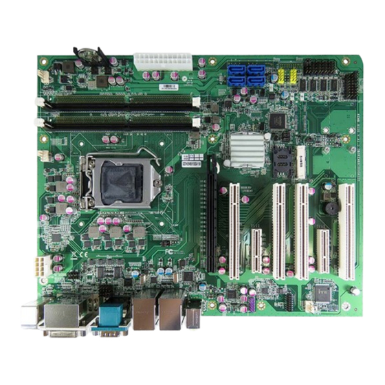
Page 23: 4/ Connector Locations
ATX-KBL-S - User Guide, Rev. 1.1 4/ Connector Locations 4.1. Top Side Figure 2: Top Side 42 28 43 36 46 44 Table 6: Jumper List Item Designation Description See Chapter Pin-9 Selection for COM3 & COM4 7.15.1 Keyboard Lock Selection 7.15.2... -
Page 24: Table 7: Top Side Internal Connector Pin Assignment
ATX-KBL-S - User Guide, Rev. 1.1 Item Designation Description See Chapter JP14 Terminator Selection for COM2 7.15.10 JP15 Pin-9 Selection for COM1 & COM2 7.15.11 Table 7: Top Side Internal Connector Pin Assignment Item Designation Description See Chapter ATX1 2x12-pin ATX Power Supply Wafer 7.1.1... - Page 25 ATX-KBL-S - User Guide, Rev. 1.1 Item Designation Description See Chapter SATA4 Serial ATA Port-4 Connector SIM1 SIM Card Holder for MPCIE1 7.11 www.kontron.com // 25...
-
Page 26: Connector Panel Side
ATX-KBL-S - User Guide, Rev. 1.1 4.2. Connector Panel Side Figure 3: Connector Panel Side Table 8: Connector Panel Side Connector List Item Designation Description See Chapter CN14 GbE LAN1 & USB3.0 Port-3, 4 6.4 & 6.5 CN15 GbE LAN2 & USB3.0 Port-1, 2 6.4 &... -
Page 27: 5/ Connector Definitions
ATX-KBL-S - User Guide, Rev. 1.1 5/ Connector Definitions The following defined terms are used within this user guide to give more information concerning the pin assignment and to describe the connector's signals. Defined Term Description Shows the pin numbers in the connector... -
Page 28: 6/ I/O-Area Connectors
ATX-KBL-S - User Guide, Rev. 1.1 6/ I/O-Area Connectors 6.1. HDMI Connector (CN22) The HDMI connector is based on standard HDMI type A. Figure 4: HDMI Connector CN22 Table 9: Pin Assignment HDMI Connector CN22 Signal Description Note TMD_Data2+ TMD_Data2–... -
Page 29: Dp Connector (Cn20)
ATX-KBL-S - User Guide, Rev. 1.1 6.2. DP Connector (CN20) The DP (DisplayPort) connector is based on standard DP female port. Figure 5: DP Connector CN20 Table 10: Pin Assignment DP Connector CN20 Signal Description Note TX0+ TX0- TX1+ TX1-... -
Page 30: Dvi-D Connector (Cn17)
ATX-KBL-S - User Guide, Rev. 1.1 6.3. DVI-D Connector (CN17) The external I/O connector panel supports one DVI-D female port. Figure 6: DVI-D Connector CN17 Table 11: Pin Assignment DVI-D Connector CN17 Signal Description Note TX2- TX2+ DDC_CLK DDC_DATA TX1-... -
Page 31: Ethernet Connectors (Cn14 - Lan1 & Cn15 - Lan2)
ATX-KBL-S - User Guide, Rev. 1.1 6.4. Ethernet Connectors (CN14 - LAN1 & CN15 - LAN2) The ATX-KBL-S supports two channels of 10/100/1000 Mbit Ethernet, which are based Intel® I219-LM and Intel® I210- AT controllers. In order to achieve the specified performance of the Ethernet port, Category 5 twisted pair cables must be used with 10/100 MByte and Category 5E, 6 or 6E with 1 Gbit LAN networks. -
Page 32: Usb Connectors (I/O Area)
ATX-KBL-S - User Guide, Rev. 1.1 6.5. USB Connectors (I/O Area) The external I/O connector panel supports two dual USB 3.0 connectors. USB3.0 ports are backward compatible with USB2.0. Figure 8: USB 3.0 Connectors CN14 - USB 3.0 Port 3, 4 & CN15 - USB 3.0 Port 1 , 2 Table 13: Pin Assignment USB3.0 Connector CN14 - USB 3.0 Port 3, 4 &... -
Page 33: Figure 10: Usb 3.0 High Speed Cable
ATX-KBL-S - User Guide, Rev. 1.1 For USB 3.0 cabling it is required to use only HiSpeed USB cable, specified in USB 3.0 standard: Figure 10: USB 3.0 High Speed Cable Filler, optional UTP Signal Pair Braid SDP Signal Pair... -
Page 34: Serial Com1 Port (Cn21)
ATX-KBL-S - User Guide, Rev. 1.1 6.6. Serial COM1 Port (CN21) The external I/O connector panel supports one DB-9 RS-232/422/485 COM male port. Figure 11: Serial COM1 Port CN21 Table 15: Pin Assignment Serial COM1 Port CN21 RS232 Signal RS422 Signal... - Page 35 ATX-KBL-S - User Guide, Rev. 1.1 Signal Description Data Carrier Detect, indicates that the modem or data set has detected the data carrier. Ring Indicator, indicates that the modem has received a ringing signal from the telephone line. TX+/- Transmitted Data differential pair sends data to the communications link.
-
Page 36: Audio Jack (Cn18)
ATX-KBL-S - User Guide, Rev. 1.1 6.7. Audio Jack (CN18) The external I/O connector panel supports one 3.5 mm dual-port Azalia audio phone jack for headset and microphone. Figure 12: Audio Jack CN18 Table 17: Pin Assignment Audio Jack CN18... -
Page 37: Ps/2 Keyboard & Mouse Mini-Din Connector (Cn19)
ATX-KBL-S - User Guide, Rev. 1.1 6.8. PS/2 Keyboard & Mouse Mini-DIN Connector (CN19) The external I/O connector panel supports one dual-port PS/2 keyboard & mouse Mini-DIN connector. Figure 13: PS/2 Keyboard & Mouse Mini-DIN Connector CN19 Table 18: Pin Assignment PS/2 Keyboard & Mouse Mini-DIN Connector CN19... -
Page 38: 7/ Internal Connectors
ATX-KBL-S - User Guide, Rev. 1.1 7/ Internal Connectors 7.1. Power Connector Power connector must be used to supply the board with ATX power supply. Hot plugging any of the power connector is not allowed. Hot plugging might damage the board. In other words, turn off main supply etc. to make sure all the power lines are turned off when connecting to the motherboard. -
Page 39: 2X4-Pin Atx Power Supply Wafer (Atx2)
ATX-KBL-S - User Guide, Rev. 1.1 Signal Description Ground Power -5 V Power +5 V Power +5 V Power +5 V Ground 7.1.2. 2x4-pin ATX Power Supply Wafer (ATX2) Figure 15: 2x4-pin ATX Power Supply Wafer ATX2 Table 20: Pin Assignment ATX2... - Page 40 ATX-KBL-S - User Guide, Rev. 1.1 Signal Description Battery- www.kontron.com // 40...
-
Page 41: Fan Wafers (Fan1, Fan2 & Fan3)
ATX-KBL-S - User Guide, Rev. 1.1 7.2. Fan Wafers (FAN1, FAN2 & FAN3) The CPU FAN Wafer (FAN2) is used for the connection of the FAN for the CPU while the System FAN Wafer (FAN1) and AUX FAN Wafer (FAN3) for the connection of the FAN for the system. -
Page 42: Sata (Serial Ata) Disk Interfaces (Sata1, Sata2, Sata3, Sata4, Cn1)
ATX-KBL-S - User Guide, Rev. 1.1 7.3. SATA (Serial ATA) Disk Interfaces (SATA1, SATA2, SATA3, SATA4, CN1) The SATA Port 1, Port 2, Port 3 & Port 4 connectors (SATA1, SATA2, SATA3 & SATA4) supply the data connection for the SATA hard disks and are SATA 2.0 compatible. -
Page 43: Table 27: Pin Assignment Cn1
ATX-KBL-S - User Guide, Rev. 1.1 Table 27: Pin Assignment CN1 Signal Note PETP0 PETN0 PERN0 PERP0 PETP1 PETN1 PERN1 PERP1 RESERVED PERST# DEVSLP / CLKREQ# IFDET www.kontron.com // 43... -
Page 44: Usb Connectors (Internal) (Cn2, Cn7, Cn8 & Cn9)
ATX-KBL-S - User Guide, Rev. 1.1 7.4. USB Connectors (Internal) (CN2, CN7, CN8 & CN9) USB 3.0 Port 5 and Port 6 are supplied via the internal pin header CN2 (only for models with Intel® Q170 chipset). USB 2.0 Port 7 and Port 8 are supplied via the internal pin header CN7. -
Page 45: Table 29: Pin Assignment Cn7, Cn8, Cn9
ATX-KBL-S - User Guide, Rev. 1.1 Table 29: Pin Assignment CN7, CN8, CN9 Signal Note +VBUS_A +5 V Supply for USB device +VBUS_B +5 V Supply for USB device USB_A- USB 2.0 Differential Pair (-) USB_B- USB 2.0 Differential Pair (-) USB_A+ USB 2.0 Differential Pair (+) -
Page 46: Front Panel Audio Connector (Cn16)
ATX-KBL-S - User Guide, Rev. 1.1 7.5. Front Panel Audio Connector (CN16) The front panel audio connector provides audio output (Line-Out) and microphone (Mic-In) signals through the wafer CN16. Figure 22: Front Panel Audio Connector CN16 Table 31: Pin Assignment CN16... -
Page 47: Front Panel Pin Header (Fp1 & Fp2)
ATX-KBL-S - User Guide, Rev. 1.1 7.6. Front Panel Pin Header (FP1 & FP2) Figure 23: Front Panel Pin Header FP1 RSTBTN SPKR HLED Table 32: Pin Assignment FP1 Signal Note Reset Button + Speaker + Reset Button - HDD LED +... -
Page 48: Table 35: Signal Description
ATX-KBL-S - User Guide, Rev. 1.1 Signal Note Power Button + Power Button - Power LED - SM ALERT# BAT_LOW# SMBus Data SMBus Clock Table 35: Signal Description Signal Description Power LED - System Power LED. The power LED lights up when users turn on the system power, and blinks when the system is in sleep mode. -
Page 49: Serial Com2 - Com6 Ports (Cn12, Cn3, Cn4, Cn5 & Cn6)
ATX-KBL-S - User Guide, Rev. 1.1 7.7. Serial COM2 - COM6 Ports (CN12, CN3, CN4, CN5 & CN6) One RS232/422/485 COM port is supplied via the internal pin header CN12. Four RS232 COM ports are supplied via the internal pin header CN3, CN4, CN5 & CN6. -
Page 50: Table 38: Pin Assignment Com5, Com6 (Cn5, Cn6)
ATX-KBL-S - User Guide, Rev. 1.1 RS232 Signal Note NC, Key *: Pin configuration can be selected by Jumper JP1. Table 38: Pin Assignment COM5, COM6 (CN5, CN6) RS232 Signal Note NC, Key The COM ports need to install an OS patch from ITE. The patch is only available for Windows and is not available Linux. -
Page 51: Vga Connector (Cn13)
ATX-KBL-S - User Guide, Rev. 1.1 7.8. VGA Connector (CN13) One VGA connector is supplied via the internal pin header CN13. Figure 26: VGA Connector CN13 Table 40: Pin Assignment CN13 Signal Description Analogue output carrying the red colour values. (75 Ohm cable impedance). -
Page 52: Digital Input / Output Pin Header (Cn10)
ATX-KBL-S - User Guide, Rev. 1.1 7.9. Digital Input / Output Pin Header (CN10) Figure 27: Digital Input / Output Pin Header CN10 Table 41: Pin Assignment CN10 Signal Note DIO_0 DIO_8 DIO_1 DIO_9 DIO_2 DIO_10 DIO_3 DIO_11 DIO_4 DIO_12... -
Page 53: Mpcie Slot Connector (Mpcie1 & Mpcie2)
ATX-KBL-S - User Guide, Rev. 1.1 7.10. mPCIe Slot Connector (MPCIE1 & MPCIE2) Full-sized Mini-PCI Express V1.2 socket (MPCIE1). Socket MPCIE1 supports mPCIe, mSATA (only models with Intel® Q170 chipset support SATA), USB2.0 and SIM-card socket. The SIM-card socket makes it possible to use a 3G/4G- wireless modem in this mPCIe slot. -
Page 54: Table 43: Pin Assignment Mpcie2
ATX-KBL-S - User Guide, Rev. 1.1 Signal Note +3.3VSB PERp0 / SATA_RX-* Ground Ground +1.5V Ground SMB_CLK PETn0 / SATA_TX-* SMB_DATA PETp0 / SATA_TX+* Ground Ground USB_D- Ground USB_D+ +3.3VSB Ground +3.3VSB LED_WWAN# Ground / NC* LED_WLAN# Reserved LED_WPAN# Reserved +1.5V... - Page 55 ATX-KBL-S - User Guide, Rev. 1.1 Signal Note Reserved Ground Reserved +1.5V CLKREQ# Reserved Ground Reserved REFCLK- Reserved REFCLK+ Reserved Ground Reserved Reserved Ground Reserved W_Disable# Ground PERST# PERn0 / SATA_RX+* +3.3VSB PERp0 / SATA_RX-* Ground Ground +1.5V Ground SMB_CLK...
- Page 56 ATX-KBL-S - User Guide, Rev. 1.1 Signal Note Reserved LED_WPAN# Reserved +1.5V Reserved Ground Reserved +3.3VSB *: Pin configuration can be selected by Jumper JP5. www.kontron.com // 56...
-
Page 57: Sim Card Socket For Mpcie1 (Sim1)
ATX-KBL-S - User Guide, Rev. 1.1 7.11. SIM Card Socket for MPCIE1 (SIM1) Figure 29: SIM Card Socket SIM1 Table 44: Pin Assignment SIM1 Signal Description Note UIM_PWR Power +5V or +3.3V UIM_RST Reset signal UIM_CLK Clock signal Ground UIM_VPP... -
Page 58: Pci Slot (Pci1, Pci2, Pci3 & Pci4)
ATX-KBL-S - User Guide, Rev. 1.1 7.12. PCI Slot (PCI1, PCI2, PCI3 & PCI4) The ATX-KBL-S supports four 32-bit 33 MHz PCI cards via Slot PCI1, PCI2, PCI3 & PCI4. Figure 30: PCI Slot PCI1, PCI2, PCI3, PCI4 Table 45: Pin Assignment PCI1, PCI2, PCI3, PCI4... - Page 59 ATX-KBL-S - User Guide, Rev. 1.1 Side B Side A Signal Description Signal Description Reserved +3.3VAUX +3.3 V auxiliary power Ground RST# Reset Clock +5 V power Ground GNT# Grant PCI use REQ# Request Ground +5 V power PME# Power Management Event...
- Page 60 ATX-KBL-S - User Guide, Rev. 1.1 Side B Side A Signal Description Signal Description AD[05] Address / Data 05 AD[04] Address / Data 04 AD[03] Address / Data 03 Ground Ground AD[02] Address / Data 02 AD[01] Address / Data 01...
-
Page 61: Pci Express X4 Slot (Pcie1 & Pcie2)
7.13. PCI Express x4 Slot (PCIE1 & PCIE2) The ATX-KBL-S supports two PCI Express x4 via slot PCIE1 and PCIE2. The 4-lane (x4) PCI Express (PCIE1 & PCIE2) port can be used for external PCI Express cards inclusive graphics card. - Page 62 ATX-KBL-S - User Guide, Rev. 1.1 Side B Side A Signal Description Signal Description PRSNT2# Hot plug presence detect PERX0- Ground Ground PETX1+ Transmitter Lane 1 differential pair PETX1- Ground Ground PERX1+ Receiver Lane 1 differential pair Ground PERX1- PETX2+...
-
Page 63: Pci Express X16 Slot (Peg1)
ATX-KBL-S - User Guide, Rev. 1.1 7.14. PCI Express x16 Slot (PEG1) The ATX-KBL-S supports one PCI Express x16 via slot PEG1. The 16-lane (x16) PCI Express (PEG1) port can be used for external PCI Express cards inclusive graphics card. - Page 64 ATX-KBL-S - User Guide, Rev. 1.1 Side B Side A Signal Description Signal Description SMDAT SMBus data Reserved Ground Reserved +3.3V +3.3 V power Reserved Reserved +3.3V +3.3 V power +3.3VSB +3.3 V standby power +3.3V +3.3 V power WAKE#...
- Page 65 ATX-KBL-S - User Guide, Rev. 1.1 Side B Side A Signal Description Signal Description Ground HSIP7 Receiver Lane 7 differential pair PRSNT2# Hot plug presence detect HSIN7 Ground Ground HSOP8 Transmitter Lane 8 differential pair Reserved HSON8 Ground Ground HSIP8...
-
Page 66: Switches And Jumpers
ATX-KBL-S - User Guide, Rev. 1.1 7.15. Switches and Jumpers The product has several jumpers which must be properly configured to ensure correct operation. Figure 33: Jumper Connector For a three-pin jumper (see Figure 35), the jumper setting is designated “1-2” when the jumper connects pins 1 and 2. -
Page 67: Keyboard Lock Selection (Jp2)
ATX-KBL-S - User Guide, Rev. 1.1 “X” = Jumper set (short) and “-” = jumper not set (open) 7.15.2. Keyboard Lock Selection (JP2) Figure 35: Keyboard Lock Selection JP2 Table 49: Pin Assignment JP2 Jumper 1 Position Description Pin 1-2... -
Page 68: Mpcie / Msata Selection For Mpcie2 & Mpcie1 (Jp5 & Jp9)
ATX-KBL-S - User Guide, Rev. 1.1 Jumper 1 Position Description Pin 1-2 Pin 2-3 Normal (default position) Clear RTC_RST Register (board does not boot with the jumper in this position) “X” = Jumper set (short) and “-” = jumper not set (open) Do not leave the jumper in position 2-3, otherwise if the power is disconnected, the battery will fully deplete within a few weeks. -
Page 69: At / Atx Power Mode Selection (Jp7)
ATX-KBL-S - User Guide, Rev. 1.1 “X” = Jumper set (short) and “-” = jumper not set (open) 7.15.7. AT / ATX Power Mode Selection (JP7) Figure 40: AT / ATX Power Mode Selection JP7 Table 54: Pin Assignment JP7... -
Page 70: Terminator Selection For Com1 & Com2 (Jp13 & Jp14)
ATX-KBL-S - User Guide, Rev. 1.1 Table 56: Pin Assignment JP12 Jumper 1 Position Jumper 2 Position Description Pin 1-3 Pin 3-5 Pin 2-4 Pin 4-6 X8 x8 X8 x4 X8 x4 x4 “X” = Jumper set (short) and “-” = jumper not set (open) 7.15.10. -
Page 71: Table 58: Pin Assignment Jp15
ATX-KBL-S - User Guide, Rev. 1.1 Table 58: Pin Assignment JP15 Jumper 1 Position Description Pin 1-3 Pin 3-5 Pin 5-7 Pin 7-9 COM1, Pin 9 = +12V COM1, Pin 9 = +5V COM1, Pin 9 = +5V COM1, Pin 9 = RI... -
Page 72: 8/ Bios
Supervisor Password (see Security menu), press <RETURN>, and proceed with step 5. 5. A setup menu will appear. The ATX-KBL-S uEFI BIOS setup program uses a hot key-based navigation system. A hot key legend bar is located on the bottom of the setup screens. -
Page 73: Setup Menus
ATX-KBL-S - User Guide, Rev. 1.1 8.2. Setup Menus The Setup utility features shows six menus in the selection bar at the top of the screen: Main Advanced Power Security Boot Save & Exit The Setup menus are selected via the left and right arrow keys. -
Page 74: Figure 45: Bios Main Menu Screen System Data And Time
ATX-KBL-S - User Guide, Rev. 1.1 Figure 45: BIOS Main Menu Screen System Data and Time BIOS SETUP UTILITY Main Advanced Power Security Boot Save & Exit Product Information Product Name ATX-KBL-S-Q170 BIOS Version R1.06 (x64) BIOS Build Date 01/15/2016 ME FW Version 11.0.0.1178... -
Page 75: Advanced Setup Menu
ATX-KBL-S - User Guide, Rev. 1.1 8.2.2. Advanced Setup Menu The Advanced setup menu provides sub-screens and functions for advanced configurations. The following sub- screen functions are included in the menu: LAN & Audio Configuration Display Configuration ... -
Page 76: Figure 46: Bios Advanced Menu
ATX-KBL-S - User Guide, Rev. 1.1 Figure 46: BIOS Advanced Menu BIOS SETUP UTILITY Main Advanced Power Security Boot Save & Exit Onboard LAN1 Controller [Enabled] Onboard LAN1 Boot [Disabled] Onboard LAN2 Controller [Enabled] Onboard LAN2 Boot [Disabled] Audio Controller [Enabled] →... -
Page 77: Figure 47: Bios Advanced Menu - Display Configuration
ATX-KBL-S - User Guide, Rev. 1.1 Figure 47: BIOS Advanced Menu - Display Configuration BIOS SETUP UTILITY Main Advanced Power Security Boot Save & Exit Display Configuration Primary Display [Auto] → ←: Select Screen UWA Frame Buffer Size [256MB] ↑ ↓: Select Item... -
Page 78: Figure 48: Bios Advanced Menu - Super Io Configuration
ATX-KBL-S - User Guide, Rev. 1.1 Figure 48: BIOS Advanced Menu - Super IO Configuration BIOS SETUP UTILITY Main Advanced Power Security Boot Save & Exit Super IO Chip Configuration > Serial Port 1 Configuration → ←: Select Screen > Serial Port 2 Configuration ↑... -
Page 79: Figure 50: Bios Advanced Menu - Super Io Configuration - Serial Port 2 Configuration
ATX-KBL-S - User Guide, Rev. 1.1 Feature Option Description Serial Port 1 Type [RS232], [RS422], Select an appropriate type for Serial Port 1. [RS485] RS485 Duplex Mode [Half Duplex], [Full Select an appropriate RS485 Duplex Mode. Duplex] RS485 Auto Flow [Disabled], [Enabled] Select whether to enable or disable RS485 Auto Flow Control. -
Page 80: Figure 51: Bios Advanced Menu - Super Io Configuration - Serial Port 3 Configuration
ATX-KBL-S - User Guide, Rev. 1.1 Figure 51: BIOS Advanced Menu - Super IO Configuration - Serial Port 3 Configuration BIOS SETUP UTILITY Main Advanced Power Security Boot Save & Exit Serial Port 3 Configuration Serial Port [Enabled] → ←: Select Screen Device Settings IO=3E8h;... -
Page 81: Figure 53: Bios Advanced Menu - Super Io Configuration - Serial Port 5 Configuration
ATX-KBL-S - User Guide, Rev. 1.1 Feature Option Description Serial Port [Disabled], [Enabled] Select whether to enable or disable Serial Port (COM). Change Settings [Auto], [IO=2E8h; Select an optional setting for Super IO device. IRQ=7;], [IO=3E8h; IRQ=3, 4, 5, 6, 7, 9, 10, 11, 12;], [IO=2E8h;... -
Page 82: Figure 54: Bios Advanced Menu - Super Io Configuration - Serial Port 6 Configuration
ATX-KBL-S - User Guide, Rev. 1.1 Figure 54: BIOS Advanced Menu - Super IO Configuration - Serial Port 6 Configuration BIOS SETUP UTILITY Main Advanced Power Security Boot Save & Exit Serial Port 6 Configuration Serial Port [Enabled] → ←: Select Screen Device Settings IO=2E0h;... -
Page 83: Figure 55: Bios Advanced Menu - Cpu Chipset Configuration
ATX-KBL-S - User Guide, Rev. 1.1 Figure 55: BIOS Advanced Menu - CPU Chipset Configuration BIOS SETUP UTILITY Main Advanced Power Security Boot Save & Exit CPU Chipset Configuration EIST [Enabled] → ←: Select Screen Turbo Mode [Enabled] ↑ ↓: Select Item... -
Page 84: Figure 56: Bios Advanced Menu - Sata Configuration
ATX-KBL-S - User Guide, Rev. 1.1 Figure 56: BIOS Advanced Menu - SATA Configuration BIOS SETUP UTILITY Main Advanced Power Security Boot Save & Exit SATA Controller(s) SATA Controller(s) [Enabled] SATA Mode Selection [AHCI Mode] Serial ATA Port 1 Empty... -
Page 85: Figure 57: Bios Advanced Menu - Usb Configuration
ATX-KBL-S - User Guide, Rev. 1.1 Figure 57: BIOS Advanced Menu - USB Configuration BIOS SETUP UTILITY Main Advanced Power Security Boot Save & Exit USB Configuration USB Devices: → ←: Select Screen None ↑ ↓: Select Item Enter: Select... -
Page 86: Figure 58: Bios Advanced Menu - Amt Configuration
ATX-KBL-S - User Guide, Rev. 1.1 Figure 58: BIOS Advanced Menu - AMT Configuration* BIOS SETUP UTILITY Main Advanced Power Security Boot Save & Exit AMT Configuration Intel AMT [Enabled] → ←: Select Screen Un-Configure ME [Disabled] ↑ ↓: Select Item Enter: Select +/-: Change Opt. -
Page 87: Figure 59: Bios Advanced Menu - Tpm Configuration
ATX-KBL-S - User Guide, Rev. 1.1 Figure 59: BIOS Advanced Menu - TPM Configuration* BIOS SETUP UTILITY Main Advanced Power Security Boot Save & Exit TPM Configuration Security Device Support [Disabled] → ←: Select Screen Current Status Information ↑ ↓: Select Item Enter: Select +/-: Change Opt. -
Page 88: Figure 60: Bios Advanced Menu - Dio Configuration
ATX-KBL-S - User Guide, Rev. 1.1 Figure 60: BIOS Advanced Menu - DIO Configuration BIOS SETUP UTILITY Main Advanced Power Security Boot Save & Exit DIO Configuration User Configuration [Disabled] DIO_0* [Output High] DIO_1* [Output High] DIO_2* [Output High] DIO_3*... - Page 89 ATX-KBL-S - User Guide, Rev. 1.1 Feature Option Description User Configuration [Enabled], [Disabled] Select whether or not to allow user to set the DO pin output value. DIO_0..15 [Output Low], [Output Set up the DIO pin input / output value.
-
Page 90: Figure 61: Bios Advanced Menu - H/W Monitor
ATX-KBL-S - User Guide, Rev. 1.1 Figure 61: BIOS Advanced Menu - H/W Monitor BIOS SETUP UTILITY Main Advanced Power Security Boot Save & Exit PC Health Status CPU Warning Temperature [Disabled] > Smart FAN Configuration CPU Temperature : +19 C... - Page 91 ATX-KBL-S - User Guide, Rev. 1.1 BIOS SETUP UTILITY Main Advanced Power Security Boot Save & Exit Version 2.17.1254. Copyright (C) 2016, American Megatrends, Inc. Feature Option Description CPU FAN Setting [Manual], [Smart] Switch the CPU FAN control mode. SYS FAN Setting [Manual], [Smart] Switch the SYS FAN control mode.
-
Page 92: Power Setup Menu
ATX-KBL-S - User Guide, Rev. 1.1 8.2.3. Power Setup Menu The Power setup menu provides functions and a sub-screen for power configurations. The following sub-screen function is included in the menu: WatchDog Timer Configuration Figure 62: BIOS Power Setup Menu... - Page 93 ATX-KBL-S - User Guide, Rev. 1.1 Feature Option Description Device Resume By Ring [Disabled], [Enabled] Select whether to enable or disable Wake from Ring Device. Device Resume By RTC Alarm [Disabled], [Enabled] Select whether to enable or disable Wake Up on Alarm, to turn on your system on a special day of the month.
-
Page 94: Figure 63: Bios Power Setup Menu - Watchdog Timer Configuration
ATX-KBL-S - User Guide, Rev. 1.1 Figure 63: BIOS Power Setup Menu - WatchDog Timer Configuration BIOS SETUP UTILITY Main Advanced Power Security Boot Save & Exit WatchDog Timer Configuration WDT Function [Disabled] → ←: Select Screen ↑ ↓: Select Item Enter: Select +/-: Change Opt. -
Page 95: Security Setup Menu
The Security setup menu provides information about the passwords and functions for specifying the security settings. The passwords are case-sensitive. The ATX-KBL-S provides no factory-set passwords. If there is already a password installed, the system asks for this first. To clear a password, simply enter nothing and acknowledge by pressing <RETURN>. -
Page 96: Remember The Password
ATX-KBL-S - User Guide, Rev. 1.1 8.2.4.1. Remember the password It is highly recommended to keep a record of all passwords in a safe place. Forgotten passwords results in being locked out of the system. If the system cannot be booted because the User Password or the Supervisor Password are not know, contact Kontron Support for further assistance. -
Page 97: Boot Setup Menu
ATX-KBL-S - User Guide, Rev. 1.1 8.2.5. Boot Setup Menu The boot setup menu lists the for boot device priority order, that is generated dynamically. Figure 65: BIOS Boot Setup Menu BIOS SETUP UTILITY Main Advanced Power Security Boot Save & Exit... -
Page 98: Save & Exit Setup Menu
ATX-KBL-S - User Guide, Rev. 1.1 8.2.6. Save & Exit Setup Menu The exit setup menu provides functions for handling changes made to the UEFI BIOS settings and the exiting of the setup program. Figure 66: BIOS Boot Setup Menu... -
Page 99: Appendix A: List Of Acronyms
ATX-KBL-S - User Guide, Rev. 1.1 Appendix A: List of Acronyms The following table does not contain the complete acronyms used in signal names, signal type definitions or similar. A description of the signals is included in the I/O Connector and Internal connector chapters within this user guide. -
Page 100: About Kontron
Kontron is a listed company. Its shares are traded in the Prime Standard segment of the Frankfurt Stock Exchange and on other exchanges under the symbol "KBC". For more information, please visit: www.kontron.com...
Need help?
Do you have a question about the ATX-KBL-S and is the answer not in the manual?
Questions and answers