
Related Manuals for Sierra Wireless AirLink GL8200


Summary of Contents for Sierra Wireless AirLink GL8200
- Page 1 WWW.INFOPULSAS.LT / info@infopulsas.lt Product Technical Specification and User Guide AirLink GL8200 4116298 November 07, 2016...
- Page 2 Data may be delayed, corrupted (i.e., have errors) or be totally lost. Although significant delays or losses of data are rare when wireless devices such as the Sierra Wireless modem are used in a normal manner with a well-constructed network, the Sierra Wireless modem should not be used in situations where failure to transmit or receive data could result in damage of any kind to the user or any other party, including but not limited to personal injury, death, or loss of property.
- Page 3 This product may contain technology developed by or for Sierra Wireless Inc. ® This product includes technology licensed from QUALCOMM This product is manufactured or sold by Sierra Wireless Inc. or its affiliates under one or more patents licensed from InterDigital Group and MMP Portfolio Licensing. Copyright ©...
- Page 4 Product Technical Specification and User Guide Document History Version Date Updates September 03, 2014 Creation Updated: March 17, 2015 2.2.1.1 Power Supply Table 29 Handling Resistance Stress Tests April 01, 2015 Updated Figure 3 Mechanical Drawing May 04, 2015 Updated section 8 Certification Compliance and Recommended Standards Updated: ...
-
Page 5: Table Of Contents
Contents 1. OVERVIEW ......................10 1.1. General Information ......................10 1.1.1. Physical Dimensions ....................10 1.1.2. RF Features ......................11 1.1.3. Interfaces........................11 1.1.4. Connection Interfaces ....................11 1.1.5. Environmental Compliance ..................11 1.1.5.1. RoHS Compliance ................... 11 1.1.5.2. Disposing of the Product ................. 12 1.2. - Page 6 Product Technical Specification and User Guide 4.6. Echo Function ........................31 5. TROUBLESHOOTING THE GL8200 ..............32 5.1. No Communications with the GL8200 through the Serial Link........32 Receiving an “ERROR” Message ..................33 5.2. Receiving a “NO CARRIER” Message ................33 5.3.
- Page 7 Operating System Upgrade ..................... 51 12.2. Firmware Upgrade ......................51 13. REFERENCES ....................52 13.1. Sierra Wireless Reference Documentation ..............52 13.2. General Reference Documentation ................. 52 13.3. List of Abbreviations ......................52 14. SAFETY RECOMMENDATIONS (FOR INFORMATION ONLY) ....... 55 14.1.
- Page 8 List of Figures Figure 1. AirLink GL8200 Modem ....................10 Figure 2. Functional Architecture ....................12 Figure 3. Mechanical Drawing ......................14 Figure 4. GL8200 Front View ......................16 Figure 5. GL8200 Back View ......................18 Figure 6. Pin Assignment of the 8-pin Micro-Fit Connector ............18 Figure 7.
- Page 9 List of Tables Table 1. Box Casing Properties ..................... 10 Table 2. Supported Bands/Connectivity ..................12 Table 3. Available Interface Signals ....................16 Table 4. SIM Interface Electrical Characteristics ................17 Table 5. LED Status ........................17 Table 6. Micro-Fit Connector Pin Description................18 Table 7.
-
Page 10: Overview
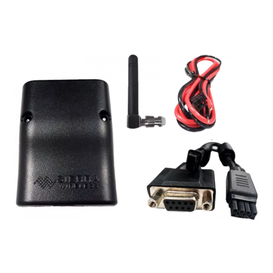
1. Overview The AirLink GL8200 is a wireless modem that allows users to connect to a wireless network by plugging in a Micro-Fit cable and an RF antenna. It offers data connectivity on GPRS, EDGE, WCDMA, HSDPA and HSUPA networks; and was designed by using the AirPrime HL8548 embedded module. -
Page 11: Rf Features
Product Technical Specification and Overview User Guide 1.1.2. RF Features GSM/GPRS/EDGE 2 Watts GSM850 and EGSM 900 radio section 1 Watt DCS and PCS radio section Hardware GPRS/EDGE class 33 capable WCDMA Penta-band UMTS WCDMA FDD (850 MHz (B5/B6), 900MHz (B8), 1900 MHz (B2), 2100MHz (B1)) ... -
Page 12: Disposing Of The Product
Product Technical Specification and Overview User Guide 1.1.5.2. Disposing of the Product This electronic product is subject to the EU Directive 2012/19/EU for Waste Electrical and Electronic Equipment (WEEE). As such, this product must not be disposed of at a municipal waste collection point. -
Page 13: Operating System
Product Technical Specification and Overview User Guide RF Band Transmit band (Tx) Receive band (Rx) Maximum Output Power GSM 850 824 to 849 MHz 869 to 894 MHz 2 Watts GSM, GPRS and EDGE E-GSM 900 880 to 915 MHz 925 to 960 MHz 2 Watts GSM, GPRS and EDGE DCS 1800... -
Page 14: Mechanical Specifications
Product Technical Specification and Overview User Guide 1.3. Mechanical Specifications 1.3.1. Mechanical Drawings Figure 3. Mechanical Drawing 4116298 Rev 7.0 November 07, 2016... -
Page 15: Product Color
Product Technical Specification and Overview User Guide 1.3.2. Product Color The GL8200 comes in: OSAKI BLACK Muncell 10B 1.5/0.5 DIC 581B (PANTONE 426C) C5%M5%Y0or5%K90% R24G25B26 HTML: #18191A 4116298 Rev 7.0 November 07, 2016... -
Page 16: Interfaces/Peripherals
2. Interfaces/Peripherals This section describes the different connectors, interfaces and peripherals that connect with the modem. The modem is distributed in the market as a finished product with the following interfaces: an 8-pin Micro-Fit Connector an FME RF Connector ... -
Page 17: Flash Led
Product Technical Specification and Interfaces/Peripherals User Guide The SIM uses five SIM signals, namely: SIM-VCC, which is the SIM power supply SIM-RST, which is reset SIM-CLK, is clock SIM-IO, as the I/O port SIM-DET, for SIM detection Refer to the following table for the electrical characteristics of the SIM interface. -
Page 18: Back Interface
Product Technical Specification and Interfaces/Peripherals User Guide 2.2. Back Interface RF Interface 8-pin Micro-Fit Connector Figure 5. GL8200 Back View 2.2.1. 8-pin Micro-Fit Connector The 8-pin Micro-Fit connector is used for the following connections: External DC power supply connection with voltage from 4.75V to 32V ... -
Page 19: Power Supply
Product Technical Specification and Interfaces/Peripherals User Guide 2.2.1.1. Power Supply The GL8200 is supplied by an external DC voltage (VIN-VBUS) that ranges from 4.75V to 32V at 2.2A. This input is available on the modem from the 8-pin Micro-Fit connector. Table 7. -
Page 20: Figure 7. 5-Wire Rs232 Serial Link Signals
Product Technical Specification and Interfaces/Peripherals User Guide RS232-TXD RS232-RXD RS232-RTS Modem (DCE) RS232-CTS RS232-DTR Figure 7. 5-wire RS232 Serial Link Signals 2.2.1.2.1. Pin Description Table 9. Serial Link Pin Description from the Micro-Fit Connector (CN201) Pin # Signal* I/O** I/O Type Reset State Description RS232-CTS... -
Page 21: Figure 8. 4-Wire Serial Link Implementation
Product Technical Specification and Interfaces/Peripherals User Guide RS232-TXD RS232-RXD RS232-RTS Modem (DCE) RS232-CTS RS232-DTR Figure 8. 4-wire Serial Link Implementation Note: The RS232-DTR signal must be managed following the V24 protocol signaling if the Sleep Mode and Serial Port Shutdown features are to be used. 2.2.1.2.3. -
Page 22: Rf Interface
Product Technical Specification and Interfaces/Peripherals User Guide 2.2.2. RF Interface The antenna connector allows the transmission of radio frequency (RF) signals from the device to an external customer supplied antenna. The connector is an FME Coaxial Connector (male). The nominal impedance of the antenna interface is 50Ω. Table 10. - Page 23 Product Technical Specification and Interfaces/Peripherals User Guide GSM850 and EGSM900 and PCS1900 and Characteristics DCS1800 WCDMA B1 WCDMA B5/B6 WCDMA B8 WCDMA B2 Impedance 50Ω Rx max 1.5:1 VSWR 1.5:1 Tx max Typical radiated 0dBi in one direction at least gain Note: Both mechanical and electrical antenna adaptations are key issues in the design of the terminal.
-
Page 24: Using The Gl8200
3. Using the GL8200 3.1. Getting Started To setup the GL8200, follow the procedures shown below. 1. Insert the SIM card into the SIM card socket. (Refer to section 3.1.1 Inserting the SIM Card and 3.1.2 Extracting the SIM Card for more details on how to insert and extract the SIM card from the GL8200.) 2. -
Page 25: Inserting The Sim Card
Product Technical Specification and Using the GL8200 User Guide 3.1.1. Inserting the SIM Card In order to insert the SIM card into the GL8200, follow the procedure shown below. 1. Prepare the SIM card in the correct position as shown in the figure. -
Page 26: Extracting The Sim Card
Product Technical Specification and Using the GL8200 User Guide 3.1.2. Extracting the SIM Card In order to extract the SIM card from the GL8200, follow the procedure shown below. 1. Use a tool to further push the SIM card into the SIM holder. Push until you hear a clicking sound. -
Page 27: Communicating With The Gl8200
4. Communicating with the GL8200 After setting up the GL8200, communications can be established by directly sending AT commands to the device using terminal software such as HyperTerminal for MS Windows. The following sub- sections describe how this is done. 4.1. -
Page 28: Checking The Pin Code Status
Product Technical Specification and Communicating with the GL8200 User Guide For more information about AT commands applicable to the GL8200, please refer to the commands marked as supported by HL8548 in document [2] AirPrime HL6 and HL8 Series AT Commands Interface Guide. -
Page 29: Verify The Network Registration
Product Technical Specification and Communicating with the GL8200 User Guide For more information about AT commands applicable to the GL8200, please refer to the commands marked as supported by HL8548x in document [2] AirPrime HL6 and HL8 Series AT Commands Interface Guide. -
Page 30: Main At Commands For The Gl8200
Product Technical Specification and Communicating with the GL8200 User Guide 4.5. Main AT Commands for the GL8200 The table below lists the main AT commands required for starting the GL8200. Table 15. Main AT Commands for the GL8200 Description AT Commands Response Notes PIN Code is accepted. -
Page 31: Echo Function
Product Technical Specification and Communicating with the GL8200 User Guide 4.6. Echo Function If no echo is displayed when entering an AT command, it could mean either of the following: The "local echo" parameter of your communication software such as HyperTerminal, is disabled. -
Page 32: Troubleshooting The Gl8200
5. Troubleshooting the GL8200 This section of the document describes possible problems that might be encountered when using the GL8200 and their corresponding solutions. To read about other troubleshooting information, refer to the Sierra Wireless Source. 5.1. No Communications with the GL8200 through... -
Page 33: Receiving An "Error" Message
Product Technical Specification and Troubleshooting the GL8200 User Guide Receiving an “ERROR” Message 5.2. The GL8200 returns an "ERROR" message (in reply to an AT command) in the following cases: The AT command syntax is incorrect. In this case, check the command syntax applicable to the HL8548x as specified in document [2] AirPrime HL6 and HL8 Series AT Commands Interface Guide. -
Page 34: Resetting The Gl8200
Product Technical Specification and Troubleshooting the GL8200 User Guide If the GL8200 Then ask Action returns Is the SIM card configured for Configure the SIM card for data/fax calls. (Ask data/fax calls? your network provider if necessary). Is the selected bearer type Ensure that the selected bearer type is "NO CARRIER"... -
Page 35: Power Consumption
6. Power Consumption 6.1. Consumption Measurement Procedure This chapter describes the procedure for consumption measurement which is used to obtain the modem’s consumption specifications. The modem consumption specification values are measured for all operating modes available on this product. For more information about the different operating modes, refer to section 6.2 Operating Modes. -
Page 36: Sim Cards
Product Technical Specification and Power Consumption User Guide The 66321D power supply is used to supply the modem, and it could also be used to measure the total current drain by the device. The “current measuring power supply” is also connected and controlled by the computer (GPIB control not shown in the previous figure). -
Page 37: Operating Modes
Product Technical Specification and Power Consumption User Guide 6.2. Operating Modes Power consumption levels of the modem also vary depending on the operating mode used. Refer to the table below for the different kinds of operating modes available. Table 20. Operating Modes Mode Description... -
Page 38: Serial Port Shutdown Mode
Product Technical Specification and Power Consumption User Guide 6.2.2. Serial Port Shutdown Mode The modem could be configured to shut down the serial link interface while there is no traffic on the serial link channel by the following AT command: ... - Page 39 Product Technical Specification and Power Consumption User Guide ave rage Working Parameters Unit Modes Vin = 32V Vin = 12V Vin = 4.75V Paging 9 2.48 2.73 3.99 (Rx burst occurrence ~2s) Paging 2 2.54 2.89 4.29 SLEEP Mode (Rx burst occurrence ~0,5s) WCDMA DRX9 2.49 2.67...
-
Page 40: Reliability Compliance And Recommendations
7. Reliability Compliance and Recommendations 7.1. Environmental Specifications The modem is compliant with the following operating classes. The table below lists the ideal temperature range of the environment. Table 22. Operating Class Temperature Range Conditions Temperature Range Operating/Class A -20 °C to +55°C Operating/Class B -30 °C to +75°C Storage... -
Page 41: Reliability Prediction Model
Product Technical Specification and Reliability Compliance and User Guide Recommendations 7.2. Reliability Prediction Model 7.2.1. Life Stress Test The following tests the product performance. Table 24. Life Stress Test Designation Condition Standard: N/A Performance Test Special conditions: Temperature: Class A: -20°C to +55°C ... -
Page 42: Corrosive Resistance Stress Test
Product Technical Specification and Reliability Compliance and User Guide Recommendations 7.2.3. Corrosive Resistance Stress Test The following tests the modem’s resistance to corrosive atmosphere. Table 26. Corrosive Resistance Stress Test Designation Condition Humidity Test Standard: IEC 60068-2-3, Test Ca Special conditions: ... -
Page 43: Mechanical Resistance Stress Tests
Product Technical Specification and Reliability Compliance and User Guide Recommendations 7.2.5. Mechanical Resistance Stress Tests The following tests the modem’s resistance to vibrations and mechanical shocks. Table 28. Mechanical Resistance Stress Tests Designation Condition Standard: IEC 60068-2-6, Test Fc Special conditions: ... -
Page 44: Handling Resistance Stress Tests
Product Technical Specification and Reliability Compliance and User Guide Recommendations 7.2.6. Handling Resistance Stress Tests The following tests the modem’s resistance to handling malfunctions and damage. Table 29. Handling Resistance Stress Tests Designation Condition Standard: IEC 61000-4-2 ESD Test Special conditions: ... -
Page 45: Certification Compliance And Recommended Standards
8. Certification Compliance and Recommended Standards The GL8200 is compliant with the following requirements. Table 30. Standards Conformity for the GL8200 Domain Applicable Standard EN 60950-1:2006 +A11:2009 +A1:2010 +A12:2011 Safety standard AS/NZS 60950.1:2003 Amdt 1:2006 Amdt 2:2008 Amdt 3:2008 Health standard (EMF Exposure Evaluation) EN 62311 (ed. -
Page 46: Cables And Accessories
9. Cables and Accessories 9.1. Adaptive Cable The adaptive cable provides a serial interface and is used as the power source of the GL8200. It has three edges/plugs. 8-pin Micro-Fit Edge DB9 Edge 2-pin Micro-Fit Edge Figure 11. Adaptive Cable for the GL8200 9.1.1. -
Page 47: Db9 Edge
Product Technical Specification and Cables and Accessories User Guide Pin Number Signal Description RS232-TXD Main RS232 Transmit Serial Data RS232-DTR Main RS232 Data Terminal Ready Ground Connection Power Supply with a 4.75 – 32V DC input Ground Connection Refer to Table 6 Micro-Fit Connector Pin Description for more information about the pin assignments and description. -
Page 48: 2-Pin Micro-Fit Edge
Product Technical Specification and Cables and Accessories User Guide 9.1.3. 2-pin Micro-Fit Edge Figure 14. 2-pin Micro-Fit Edge of the Adaptive Cable Figure 15. Pin Assignment of the 2-pin Micro-Fit Edge Refer to the following table for the pin description of the 2-pin Micro-Fit Edge of the Adaptive cable. Table 33. -
Page 49: Mechanical Constraints
10. Mechanical Constraints 10.1. Micro-Fit Connector The following table lists the mechanical constraints that must be taken into account when using the 8- pin Micro-Fit connector. Table 35. Micro-Fit Connector Mechanical Constraints Description Mechanical Limit Notes MINIMUM withdrawal force: 3.7N This is the least amount of force needed to unplug (0.8lbf) the cable from the 8-pin Micro-Fit connector. -
Page 50: Protections
11. Protections 11.1. Power Supply Sierra Wireless recommends having a 1000mA/250V slow break fuse bonded to the power supply cable which can protect the modem’s internal electronic components from over-current consumption. 11.2. Electrostatic Discharge The GL8200 withstands ESD according to IEC 1000-4-2 requirements for all accessible parts of the GL8200 except the RF part, which only protects: ... -
Page 51: Upgrade Guidelines
12. Upgrade Guidelines 12.1. Operating System Upgrade The GL8200’s operating system is stored in flash memory and can be easily upgraded. The operating system file can be downloaded into the GL8200 using FLASH tools. Listed below are the serial signals required to proceed the firmware upgrading: ... -
Page 52: References
For more details, several reference documents can be consulted. The Sierra Wireless documents referenced herein are provided in the Sierra Wireless documentation package; however, the general reference documents which are not Sierra Wireless owned are not provided in the documentation package. - Page 53 Product Technical Specification and References User Guide Abbreviation Definition Digital Cellular System Dynamic Range Data Set Ready Data Terminal Equipment Data Terminal Ready Enhanced Full Rate E-GSM Extended GSM Electromagnetic Compatibility Electromagnetic Interference Enhanced Message Service Enable Electrostatic Discharges FIFO First In First Out Full Rate Full Type Approval...
- Page 54 Product Technical Specification and References User Guide Abbreviation Definition Personal Computer Printed Circuit Board Personal Digital Assistant Power Frequency Modulation Phase Shift Modulation Pulse Width Modulation Random Access Memory Radio Frequency Radio Frequency Interference RHCP Right Hand Circular Polarization Ring Indicator Reset Real Time Clock RTCM...
-
Page 55: Safety Recommendations (For Information Only)
14. Safety Recommendations (For Information Only) For the efficient and safe operation of your GSM device, please read the following information carefully. 14.1. RF Safety 14.1.1. General Your GSM terminal is based on the GSM standard for cellular technology. The GSM standard is spread all over the world. -
Page 56: Antenna Care And Replacement
Product Technical Specification and Safety Recommendations User Guide (For Information Only) 14.1.4. Antenna Care and Replacement Do not use the GSM terminal with a damaged antenna. If a damaged antenna comes into contact with the skin, a minor burn may result. Replace a damaged antenna immediately. Consult your manual to see if you may change the antenna yourself. -
Page 57: Aircraft
Product Technical Specification and Safety Recommendations User Guide (For Information Only) 14.2.5. Aircraft Turn your terminal OFF before boarding any aircraft. Use it on the ground only with crew permission Do not use it in the air To prevent possible interference with aircraft systems, Federal Aviation Administration (FAA) regulations require you to have permission from a crew member to use your terminal while the aircraft is on the ground. -
Page 58: Appendix A: Packaging
15. Appendix A: Packaging GL8200 modems come in an outer box that contains two pizza boxes. Figure 18. Two Pizza Boxes in an Outer Box One pizza box contains 50 sets of adaptive cables and DC cables; while the other pizza box is foam- partitioned and contains 50 GL8200 modems. -
Page 59: Appendix B: Product Labeling
16. Appendix B: Product Labeling Two product labels are available at the back of the GL8200. 16.1. Model and MSN Label The Model and MSN label provides the following information: Product name: GL8200 CE marking with certification number ... -
Page 60: Imei And Approval Label
IC ID Japan Approval Mark Radio Certification Type Number Telecom Certification Type Number Company name (Sierra Wireless) Made in China Operator Name Figure 21. IMEI and Approval Label 4116298 Rev 7.0 November 07, 2016...
Need help?
Do you have a question about the AirLink GL8200 and is the answer not in the manual?
Questions and answers