Sign In
Upload
Download
Table of Contents
Contents
Add to my manuals
Delete from my manuals
Share
URL of this page:
HTML Link:
Bookmark this page
Add
Manual will be automatically added to "My Manuals"
Print this page
×
Bookmark added
×
Added to my manuals
Manuals
Brands
Sierra Wireless Manuals
Modem
GL6100
User manual
Sierra Wireless GL6100 User Manual
Airlink gl series
Hide thumbs
1
2
3
4
Table Of Contents
5
6
7
8
9
10
11
12
13
14
15
16
17
18
19
20
21
22
23
24
25
26
27
28
29
30
31
32
33
34
35
36
37
38
39
40
41
42
43
44
45
46
47
48
49
50
51
52
53
54
55
56
57
58
59
60
61
62
63
64
65
66
67
68
69
70
71
72
73
74
75
76
77
78
79
80
81
82
83
84
85
86
87
88
89
90
91
92
93
94
95
96
page
of
96
Go
/
96
Contents
Table of Contents
Troubleshooting
Bookmarks
Table of Contents
Important Notice
Safety and Hazards
Contact Information
Document History
Table of Contents
1 Overview
Variants
Ordering Information
Shipment Configuration
Table 1: Gl61X0 Variants with Corresponding PNMKT
Table 2: Gl61X0 Shipment Configuration
Overall Dimensions
GSM/GPRS Features
Connectors
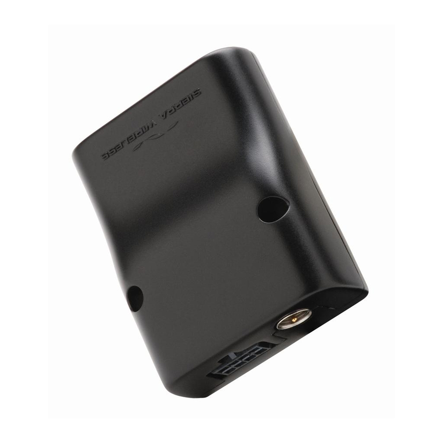
Figure 1. Gl61X0 Plug & Play Modem
Table 3: Gl61X0 Physical Dimensions
Interfaces
Environmental Compliance
Rohs Compliance
Disposing of the Product
2 Gl61X0 Feature Set
Table 4: Gl61X0 Feature Set
Supported Bands
Protection
Electrostatic Discharge
Figure 2. Adaptive Cable Fuse
GL6100 - UART Version
GL6110 - USB Version
Power Supply
Main Serial Link and USB Connection
SIM Interfaces
3 Gl61X0 Cables and Accessories
Adaptive Cable (for the GL6100)
8-Pin Micro-Fit Edge
Figure 3. Adaptive Cable for the GL6100
Figure 4. 8-Pin Micro-Fit Edge of the Adaptive Cable
DB9 Edge
Figure 5. DB9 Edge of the Adaptation Cable
Table 5: 8-Pin Micro-Fit Connector Pin Description
Table 6: DB9 Connector Pin Description
2-Pin Micro-Fit Edge
Figure 6. 2-Pin Micro-Fit Edge of the Adaptive Cable
Figure 7. Pin Assignment of the 2-Pin Micro-Fit Edge
Table 7: 2-Pin Micro-Fit Connector Pin Description
Standard DB9 Cable (for the GL6100)
Figure 8. DB9 Cable
Figure 9. Pin Assignment of the DB9 Cable
DC Cable (for the GL6100)
Figure 10. DC Cable
Figure 11. Pin Assignment of the DC Cable
Table 8: DC Cable Pin Description
AC/DC Adaptor (for the GL6100)
Figure 12. AC/DC Adaptor
Micro-Fit ® USB Cable (for the GL6110)
Figure 13. Micro-Fit ® USB Cable
Figure 14. USB Connector on Micro-Fit
Table 9: 8-Pin Micro-Fit Connector Pin Assignment
FME Antenna
Figure 15. FME Antenna
Table 10: USB Pin Assignment
Table 11: FME Antenna Characteristics
4 Functional Specifications
Functional Architecture
GL6100 Functional Architecture
Figure 16. GL6100 Functional Architecture
GL6110 Functional Architecture
Figure 17. GL6110 Functional Architecture
RF Functionalities
Operating System
Table 12: Supported RF Frequencies
5 Technical Specifications
Power Supply
GL6100 - UART Version
GL6110 - USB Version
Table 13: Power Supply Electrical Characteristics
Table 14: Effects of Power Supply Defect for the GL6100
Mechanical Specifications
Mechanical Drawing
Table 15: Effects of Power Supply Defect for the GL6100
Figure 18. Gl61X0 Mechanical Drawing
Mechanical Constraints
FME Connector
Micro-Fit Connector
Table 16: Micro-Fit Connector Mechanical Constraints
Table 17: FME RF Connector Mechanical Constraints
6 Interfaces and Peripherals
Front Interface
SIM Interface
Figure 19. Gl61X0 Front Interface
SIM Socket Pin Description
Table 18: SIM Interface Electrical Characteristics
Table 19: SIM Interface Pin Description
LED Status Indicator
Figure 20. LED State During Reset and Initialization Time
Table 20: Gl61X0 LED Status
Back Interface
8-Pin Micro-Fit Connector
Figure 21. Gl61X0 Back Interface
Figure 22. 8-Pin Micro-Fit Connector on Cable Side
Table 21: 8-Pin Micro-Fit Connections
Figure 23. Pin Assignment of the 8-Pin Micro-Fit Connector on Gl61X0
Table 22: 8-Pin Micro-Fit Connector Pin Description for the Gl61X0
Figure 24. RS-232 Serial Link Signals
Power Supply Connection
Setup Communications with the GL6100: Main Serial Link Connection (RS-232)
Table 23: Power Supply Pin Description
Table 24: RS-232 Pin Description
Figure 25. Serial Link Implementation for a 5-Wire UART
Figure 26. Serial Link Implementation for a 4-Wire UART
Figure 27. Serial Link Implementation for a 2-Wire UART
Setup Communications with the GL6110: USB Connection
RF Interface
Figure 28. USB Signals on the USB Type a Connector
Table 25: USB Pin Description on Micro-Fit
Antenna Specifications
RF Performances
Table 26: Main Receiver Parameters for the Gl61X0
Table 27: Main Transmitter Parameters for the Gl61X0
Table 28: Gl61X0 Antenna Specifications
7 Using the Gl61X0
Getting Started
Inserting the SIM Card
Extracting the SIM Card
Operational Status
8 Communicating with the Gl61X0
Communications Testing for the Gl61X0
Table 29: Basic at Commands for the Gl61X0
Verifying the Received Signal Strength
Verifying the Network Registration
Table 30: <Rssi> Value Description
Table 31: AT+CREG Main Reponses
Checking the Band Selection
Switching Bands
Table 32: AT+WMBS Responses
Table 33: AT+WMBS Band Selection
Checking the PIN Code Status
Main at Commands for the GL6100
Table 34: AT+CPIN Main Responses
Table 35: Main at Commands Used for the Gl61X0
Echo Function
9 Using the Gl61X0 with Embedded Sim
Operation
Switching between Embedded SIM and an External SIM
Table 36: AT+CPIN Main Response
Table 37: AT+WHCNF SIM Selection
Software Configuration
Table 38: AT+WHCNF Main Responses
10 Gl61X0 Maintenance
Enabling/Disabling the Flash LED
Resetting the Gl61X0
Operating System Upgrade Procedure
Table 39: Requirement of X-Modem Downloading for Gl61X0
11 Troubleshooting the Gl61X0
GL6100 - RS232 Version
No Communications with the GL6100 through the Serial Link
Table 40: no Communications with the GL6100 through the Serial Link
GL6110 - USB Version
No Communications with the GL6110 through the USB
Receiving "ERROR
Table 41: no Communications with the GL6110 through the USB
Receiving "NO CARRRIER
Table 42: Receiving a "NO CARRIER" Message
Table 43: Extended Error Codes
12 Power Consumption
Various Operating Modes
Table 44: Gl61X0 Operating Modes
Entering Active/Sleep Mode
Entering Sleep Idle Mode (Only Available on GL6100)
Using AT+W32K = 1
Using AT+W32K = 1,0
Table 45: AT+WBHV Behavior Configuration
GL6100 Power Consumption
Power Consumption Without the Sierra Wireless Software Suite
Table 46: Power Consumption Without the Sierra Wireless Software Suite (Serial Port Auto Shutdown Mode Enabled); Typical Values
Table 47: Power Consumption Without the Sierra Wireless Software Suite (Serial Port Auto Shutdown Mode Disabled); Typical Values
GL6110 Power Consumption
Power Consumption Without the Sierra Wireless Software Suite
Table 48: Power Consumption Without the Sierra Wireless Software Suite; Typical Values
Consumption Measurement Procedure
Hardware Configuration
Equipment
Figure 29. Typical Hardware Configuration for Power Consumption Measurement
SIM Cards Used
Software Configuration
Gl61X0 Configuration
Table 49: List of Recommended Equipments
Equipment Configuration
Table 50: Operating Mode Information
13 Reliability Standards: Compliance and Recommendations
Reliability Compliance
Applicable Standards Listing
Table 51: Standards Conformity for the Gl61X0
Table 52: Applicable Standards and Requirements for the Gl61X0
Environmental Specifications
Table 53: Operating Class Temperature Range
Function Status Classification
Reliability Prediction Model
Life Stress Test
Environmental Resistance Stress Test
Table 54: ISO Failure Mode Severity Classification
Table 55: Life Stress Test
Corrosive Resistance Stress Test
Thermal Resistance Cycle Stress Test
Table 56: Environmental Resistance Stress Test
Table 57: Corrosive Resistance Stress Test
Table 58: Thermal Resistance Cycle Stress Test
Mechanical Resistance Stress Tests
Table 59: Mechanical Resistance Stress Tests
Handling Resistance Stress Tests
Table 60: Handling Resistance Stress Tests
14 Recommendations When Using the Gl61X0 on Trucks
Recommended Power Supply Connection on Trucks
Figure 30. Recommended Power Supply Connection on Trucks
Technical Constraints on Trucks
Figure 31. Example of an Electrical Connection Which May Damage the Gl61X0
15 Certification Compliance and Recommended Standards
Certification Compliance
Applicable Standards Listing
Table 61: Standards Conformity for the Gl61X0
Table 62: Applicable Standards and Requirements for the Gl61X0
16 Embedded Peripherals
I/O Connector
SIM Card Socket
Table 63: 8-Pin Micro-Fit Connector
Table 64: Recommended SIM Card Socket
17 Recommended Connectors
GSM Antenna
18 Reference Documents
Sierra Wireless Software Documentation
Firmware Documentation
Other Related Documentation
General Reference Documentation
19 List of Abbreviations
20 Appendix A: Packaging
GL6100 2-Cable Package (Antenna Not Included)
GL6100 Complete Cable Package
GL6110 Package
21 Appendix B: Product Labeling
Model and MSN Label
Figure 32. Gl61X0 Model and MSN Label
IMEI and Approval Label
Figure 33. Gl61X0 IMEI and Approval Label
22 Appendix C: Safety Recommendations (for Information Only)
RF Safety
General
Exposure to RF Energy
Efficient Terminal Operation
Antenna Care and Replacement
General Safety
Driving
Electronic Devices
Vehicle Electronic Equipment
Medical Electronic Equipment
Aircraft
Children
Blasting Areas
Potentially Explosive Atmospheres
Advertisement
Quick Links
1
Gsm/Gprs Features
Download this manual
GL61x0 Product Technical
Specification and User Guide
AirLink GL Series
WA_DEV_GL6100_PTS_001
002
May 24, 2010
Table of
Contents
Previous
Page
Next
Page
1
2
3
4
5
Advertisement
Table of Contents
Need help?
Do you have a question about the GL6100 and is the answer not in the manual?
Ask a question
Questions and answers
Subscribe to Our Youtube Channel
Related Manuals for Sierra Wireless GL6100
Modem Sierra Wireless AirLink GX400 Installation Manual
(4 pages)
Modem Sierra Wireless GL6110 User Manual
Airlink gl series (96 pages)
Modem Sierra Wireless GL8200 Installation & User Manual
Aidcall touchsafe pro wireless nursecall system gsm modem (24 pages)
Modem Sierra Wireless AirLink GL8200 User Manual
(61 pages)
Modem Sierra Wireless Airlink GX450 Quick Start Manual
(10 pages)
Modem Sierra Wireless GX350 Quick Reference Card
(10 pages)
Modem Sierra Wireless AirLink GL7 00 Series Product Technical Specification And User Manual
(66 pages)
Modem Sierra Wireless Compass 597 User Manual
Sierra wireless usb modem with tru install user guide (65 pages)
Modem Sierra Wireless MP 875 User Manual
Sierra wireless modem user manual (84 pages)
Modem Sierra Wireless AirCard 595U User Manual
Sierra wireless aircard usb modem user guide 595u (44 pages)
Modem Sierra Wireless RAVEN IDEN 20070914 User Manual
Sierra wireless modem user manual (159 pages)
Modem Sierra Wireless MP 595 User Manual
Sierra wireless modem user guide mp 595 (68 pages)
Modem Sierra Wireless MP215 Installation Configuration And User’s Manual
Sierra wireless modem installation configuration and user's guide mp215 (38 pages)
Modem Sierra Wireless RavenXTV Instruction Manual
Cdma sierra wireless cellular modem (40 pages)
Modem Sierra Wireless USB 306 Quick Start Manual
Sierra wireless usb 306 modem (17 pages)
Modem Sierra Wireless WISMO218 Technical Specifications
Wireless standard modem product technical specification & customer design guidelines (110 pages)
This manual is also suitable for:
Gl6110
Table of Contents
Print
Rename the bookmark
Delete bookmark?
Delete from my manuals?
Login
Sign In
OR
Sign in with Facebook
Sign in with Google
Upload manual
Upload from disk
Upload from URL


Need help?
Do you have a question about the GL6100 and is the answer not in the manual?
Questions and answers