Table of Contents
Advertisement
Quick Links
Advertisement
Table of Contents

Related Manuals for Sierra Wireless AirLink MP


Summary of Contents for Sierra Wireless AirLink MP
- Page 1 MP for Sprint User Guide 2130795 Rev 1.0...
- Page 3 Do not operate the Sierra Wireless AirLink MP in any aircraft, whether the aircraft is on the ground or in flight. In aircraft, the Sierra Wireless AirLink MP MUST BE POWERED OFF. When operating, the Sierra Wireless AirLink MP can transmit signals that could interfere with various onboard systems.
-
Page 4: Contact Information
Sierra Wireless, registered in the European Community. AirLink™ and AceWare™ are trademarks of Sierra Wireless. Sierra Wireless, the Sierra Wireless logo, the red wave design, and the red-tipped antenna are trademarks of Sierra Wireless. ® Windows is a registered trademark of Microsoft Corporation. -
Page 5: Revision History
Preface Revision History Revision Release Changes number date 2009 ALEOS 4.0 documentation draft created. Rev 1.0 Mar.10... - Page 6 AirLink MP User Guide 2130795...
-
Page 7: Table Of Contents
Contents Introducing the MP Modem ........5 Supported CDMA radio frequencies . - Page 8 Contents Hardware and Software Installation ....... .19 Installation overview ......... . . 19 MP modem housing.
- Page 9 Contents Install the MP modem......... . 21 Step 1—Mount the MP modem .
- Page 10 AirLink MP User Guide Status indicators ..........38 Reset the MP modem .
-
Page 11: Introducing The Mp Modem
• Software • Documentation Note: Do not connect the MP modem to a USB port The Sierra Wireless MP modem provides a wireless network on a computer before connection for portable computers in vehicles or offices. installing the software. If the MP modem is installed in a vehicle, it typically is mounted in the trunk and connected to a notebook computer in the passenger compartment. -
Page 12: Supported Cdma Radio Frequencies
AirLink MP User Guide • Circuit switched (dial-up) data, using the earlier CDMA IS-95 specification, supports data connections to any dial-up service at rates up to 14.4 kbps. The MP modem is primarily designed to provide 1x or better data connections but it also allows for Circuit Switched Data (CSD) connections in areas that have CDMA IS-95 coverage but no 3G high-speed packet service. -
Page 13: Aleos
Setup Wizard • Modem Doctor These modem utilities, are free of charge to those who own Sierra Wireless AirLink modems. You can download the applications and their user guides from the Sierra Wireless AirLink Solutions web site: http://www.sierrawireless.com/ support. Contact your dealer or Sierra Wireless representative for any further information. -
Page 14: Simplified Deployment
Modem Doctor is a troubleshooting and diagnostics utility. This utility will allow you to get a log file of the MP activity which you can then send to Sierra Wireless support, erase the current configuration completely., and temporarily set the MP to a known configuration to aid in trouble shooting (SOS mode). -
Page 15: Connection Methods
Introducing the MP Modem Figure 1-2: Modem Doctor Connection methods You can connect the MP modem to a USB, Ethernet (RJ45), or serial (DB9) port on a computer. When connected to a USB or Ethernet port, the MP modem behaves like a network card. When connected to a serial port, the MP modem behaves like a dial-up modem. -
Page 16: Networking
This is achieved by using authentication algorithms and their outputs. The IPSec architecture model includes the Sierra Wireless AirLink modem as a remote gateway at one end communicating, through a VPN tunnel, with a VPN gateway at the other end. -
Page 17: Gregre
IP through the GRE tunnel. Applications Events Reporting Events Reporting is Sierra Wireless AirLink’s modem’s new software feature provided via ACEmanager and Ace View, that allows the users to generate reports from the events that take place. Event Reporting Protocol is an intuitive embedded protocol, which automatically formats the messages based on an event trigger. -
Page 18: Software
AirLink MP User Guide Software The MP modem comes with the following software: • ACEview, the software for the MP modem which allows you to manage and monitor your connections. • The driver that forms the interface between the MP modem and your Windows operating system. -
Page 19: Tools And Reference Documents
ACEview User Guide This document explains the use of this utility tools which is used to view and monitor the connection state of a Sierra Wireless AirLink device. ACEnet User Guide This document explains the use of ACEnet services for remote management of Sierra Wireless AirLink device. - Page 20 AirLink MP User Guide 2130795...
-
Page 21: Getting Started
2: Getting Started • Plan your MP modem installation This chapter provides: • Required equipment • An overview of the installation process • System • Information about the equipment you’ll need requirements • System requirements for the clients you want to use with the MP modem •... -
Page 22: What Type Of Connection(S) Do You Plan To Use
AirLink MP User Guide started, when the ignition is in accessory mode, or independently of the ignition). • If you are installing the MP modem in an office, an AC/DC adapter is available. Warning: Risk of electric shock: Only use the supply voltages listed in this user guide. -
Page 23: System Requirements
Getting Started · The Ethernet cable should have RJ-45 connectors. The MP modem’s performance is affected by the type of Ethernet card in the computer and the type of cable used. The minimum requirement for the Ethernet cable is an unshielded twisted pair (UTP) cable, category 3 or 4. For better perfor- mance, use a shielded, category 5 cable. - Page 24 AirLink MP User Guide 2130795...
-
Page 25: Hardware And Software Installation
3: Hardware and Software Installation • Installation overview • Install the MP This chapter provides instructions for installing the MP modem, modem installing the ACEview software, and activating your account. The MP modem installation should be done by a professional. Before you begin the installation, ensure that you have all the necessary components and equipment listed and have read the “Installation overview”... -
Page 26: Connector Panel
AirLink MP User Guide Connector panel The MP modem has the following connectors: WAP antenna for wireless access (RP-SMA) for MP WiFi GPS antenna (female SMA) RS-232 serial (female DB9) only USB (Type B) Ethernet I/O connector (DB15HD) Serial Host... -
Page 27: Install The Mp Modem
Hardware and Software Installation Do not connect the cable to the computer until you have installed the software. 5. Install the software. Note: Please refer to MP 597 Quick Start Guide for instructions on software installation and MP modem activation. 6. -
Page 28: Ground The Mp Modem
AirLink MP User Guide 3. Use the supplied mounting screws and washers to secure the MP modem through the holes along the edge of the case bottom. Figure 3-3: Mounting the MP modem. Arrows indicate the mounting holes. Ground the MP modem Note: Electrical installations are potentially dangerous and should be performed by personnel thoroughly trained in safe electrical wiring procedures for vehicles. -
Page 29: Step 2-Mount The Antennas And Install The Cables
Hardware and Software Installation You can also use a ground screw on the connector panel of the MP modem. Use a 16-gauge wire if you choose to use a ground screw. A ground screw is not required as long as the power harness is properly grounded. Power If you are using a ground screw, insert it here. -
Page 30: Gps Antenna
AirLink MP User Guide For more information about antennas for your installation contact your account manager. GPS antenna The GPS antenna connects to the MP modem using a male SMA connector. Contact your account manager for more information about compatible GPS antennas. -
Page 31: Step 3-Install The Power Harness
Hardware and Software Installation GPS antenna Serial Host USB Host Main Diversity Diversity RF antenna RF antenna Figure 3-5: The MP modem’s SMA connector for the GPS and AP antennas (top), and the TNC connector for the Main RF antenna (bottom right). The AP antenna must be installed by a professional and there must be a separation of at least 20 cm. -
Page 32: Vehicle Installation
5 A fuses. The black ground wire is not fused. (See Ground the power harness page 27.) Replacement power harnesses are available from Sierra Wireless. Note: The battery cable used for a car, truck, or other mobile connection must be less than 3 meters in length. -
Page 33: Ground The Power Harness
Hardware and Software Installation • Engine on only. Connect the white ignition sense wire to the vehicle’s ignition switch so that the MP modem is powered on only when the ignition key is switched to the full “On” position, that is, when the engine has been started. -
Page 34: Crimp Terminals
A serial cable (with a DB9 connector on the MP modem end). The maximum Note: 5.5-meter cable part length of the serial cable is 5.5 m (18 feet). Sierra Wireless sells suitable number: 6000083. serial cables in 5-meter (16-feet) lengths. -
Page 35: Install The Usb, Ethernet Or Serial Cable
MP modem. (The installation requires either two antennas—one Main RF and one GPS—or a single combination RF/GPS antenna.) For more information about GPS, see the Primer on GPS Operations (document #2130313) on the Sierra Wireless web site, www.sierrawireless.com. Rev 1.0 Mar.10... -
Page 36: Gps Protocols And Commands
AirLink MP User Guide GPS protocols and commands The GPS module supports two methods of reporting navigational information, Note: The “MP 3G using either the TAIP (Trimble ASCII Interface Protocol) or NMEA (National Modems TAIP Reference manual” (document Marine Electronics Association) protocols. The GPS module is pre-configured for #2130312) provides a TAIP. -
Page 37: I/O Device Installation And Configuration
Hardware and Software Installation TAIP Message Identifiers Initial Position Long Navigation Message Position/Velocity Solution Reporting Mode Reset Status Time / Date Version Number I/O device installation and configuration The I/O port on the MP modem allows for remote monitoring of gauges, sensors, and alarms. -
Page 38: Port Specifications
AirLink MP User Guide DB15HD male cable DB15HD female connector on rear of MP modem Reserved—do not connect Reserved—do not connect 3. Digital Input/Output 1 4. Digital Input 3 Reserved—do not connect Reserved—do not connect 7. Analog Input 2 8. Analog Input 4 Reserved—do not connect... -
Page 39: Example: Panic Button Connections
Hardware and Software Installation Typically a digital input device should be connected between Ground (Pin 10) and the input port (Pin 3, 4, 11, or 12). Figure 3-11: A button wired to Pin 4 (digital input) and Pin 10 (Ground). The pins report a logic high on an input of 3.45 VDC. -
Page 40: Analog Input Devices
AirLink MP User Guide Figure 3-12: Wiring for using Pin 3 (digital output) as an electronic switch. Pin 10 is Ground. The digital I/O ports provide open-collector output to a maximum of 500 mA. Analog input devices Analog input devices are those that generate a signal of varying voltage, based on the state of an instrument or gauge. -
Page 41: Step 5- Start Acemanager
Hardware and Software Installation Step 5- Start ACEmanager ACEmanager is a free utility. Follow the steps below to connect to ACEmanager. • Ensure MP connectivity to access ACEmanager. • Go to: http://192.168.13.31:9191 the first time you connect to ACEmanager. • Enter username as User and password as 12345. - Page 42 AirLink MP User Guide 2130795...
-
Page 43: Mp Modem Operation
4: MP Modem Operation • Status indicators • ACEview software Operating the MP modem requires some knowledge of both the MP modem hardware and the ACEview software. This chapter describes the basics of each. Turning the MP modem on and off If the MP modem is installed in a vehicle, the way in which the MP modem is wired determines how it is powered on and off. -
Page 44: Status Indicators
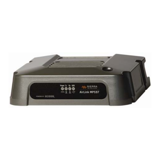
AirLink MP User Guide Status indicators The MP modem’s indicator panel includes four indicator lights.: Power indicator GPS indicator Receive (Rx) Transmit (Tx) indicator indicator Figure 4-1: The indicator panel of the MP modem. The following table shows the behavior of the LEDs during normal MP modem... -
Page 45: Aceview Software
Launching ACEview Start > Programs > To launch ACEview, start ACEview by choosing Sierra Wireless Inc > ACEview > ACEview , or double click the desktop shortcut. Please refer to the AceView User Guide Rev A. Rev 1.0 Mar.10... - Page 46 AirLink MP User Guide 2130795...
-
Page 47: Configuring The Mp Modem
5: Configuring the MP modem • ACEmanager • Using a Terminal Application with With ALEOS as its “brain”, the MP is a highly configurable device. AT Commands To configure your MP, you have two options. You can use the • AT Command configuration and management applications of the AceWare suite or you can use a terminal emulator application such as HyperTerminal, PuTTY, or many others. - Page 48 Figure 5-1: HyperTerminal 1. Choose a name and icon for your connection a. Choose a name for your connection, such as MP or Sierra Wireless AirLink Solutions. The name and icon are only for your own reference so you can find the connection at a later date.
- Page 49 Configuring the MP modem Figure 5-2: Connect To b. Change or verify the settings: · Bits per Second: 115200 (default) · Data Bits: 8 · Parity: None · Stop Bits: 1 · Flow Control: Hardware. Figure 5-3: Port Settings If you have configured the MP for settings different than the defaults for Bits per Tip: Second, Data Bits, Parity, and/or Stop Bits, you will need to use your changed settings.
- Page 50 AirLink MP User Guide 192.168.14.31 Select OK. 3. Connected Connecting on USB/net will prompt for password. Figure 5-4: HyperTerminal : TCP/IP connected 2130795...
-
Page 51: At Command
Configuring the MP modem Figure 5-5: HyperTerminal : connected a. If you are prompted for a password, enter 12345 (default password). You will not be prompted for a password if you connect using a COM port. Tip: b. Type AT and press Enter. You should get a reply of “OK” or “0”. c. - Page 52 AirLink MP User Guide • AT Commands are not case sensitive. A capital “E” is the same as a lower- case “e”. • When you are using a terminal connection, if you enter a command which is recognized by the MP, it will respond with “OK”. If the command is not recog- nized, the response will be “ERROR”.
-
Page 53: Support And Warranty
The sole responsibility of Sierra Wireless, Inc. under this warranty is limited to either repair or, at the option of Sierra Wireless, Inc., replacement of the MP modem. There are no expressed or implied warranties, including those of fitness for a particular purpose or merchantability, which extend beyond the face hereof. - Page 54 AirLink MP User Guide 2130795...
-
Page 55: Technical Specifications
B: Technical Specifications This chapter provides technical data for the MP modem. Note: The technical specifications are subject to change without notice. Regulatory, radio frequency and electrical specifications Approvals Industry Canada EU RoHS Network compliance CDMA 1xEV-DO Revision A (IS-856-A) CDMA 1xEV-DO Revision 0 (IS-856) CDMA 1X (IS-2000) CDMA IS-95A... -
Page 56: Environmental Specifications
AirLink MP User Guide Environmental specifications Operating MIL 810F, Method 501.4, 502.4 temperature -30°C to +70°C (-22°F to +158°F) Storage MIL 810F, Method 501.4, 502.4 temperature -40°C to +85°C (-40°F to +185°F) Humidity 95% RH non-condensing MIL 810F, Section 507.4 Drop MIL 810F, Section 516.5 D... -
Page 57: Weight And Dimensions
Weight and dimensions Weight and dimensions Weight 0.9 kg (2 lbs) Height 49 mm (1.93 in) Width 138 mm (5.43 in) Length 176 mm (6.93 in) Case material Metal Case surface Scratch-resistant powder coat paint Host interfaces Serial One — DB9 female One —... -
Page 58: Gps Specifications
AirLink MP User Guide GPS specifications Satellite channels 12 channel, continuous tracking Protocols TSIP, TAIP, NMEA 0183 V3.0 Acquisition times Re-acquisition: 2 sec. Hot start: 9 sec. Warm start: 35 sec. Cold start: 39 sec. Accuracy Horizontal: < 3 m (50%), < 8 m (90%) Altitude: <... -
Page 59: Wireless Access Point Specifications
Wireless access point specifications Wireless access point specifications Standards IEEE 802.11b, IEEE 802.11g, IEEE 802.11i Channels 1 (2.412 GHz) to 11 (2.462 GHz) Band 2.4 GHz Wireless-G Channels spacing 5 MHz Security features Open WPA (Wireless Protected Access) WPA2 Open WEP (64-bit and 128-bit) Shared WEP (64-bit and 128-bit) Encryption Wireless Equivalent Privacy (WEP) - Page 60 AirLink MP User Guide 2130795...
-
Page 61: Regulatory Information
Main RF antenna and the body not expressly approved by Sierra Wireless, Inc. could of the user and any nearby persons at all times and in all applications and uses. void compliance with... -
Page 62: Important Note
AirLink MP User Guide The Main RF Main RF antenna must be mounted such that there is a separation distance of at least 20 cm (8 inches) between the Main RF antenna and the body of the user or any nearby persons.
Need help?
Do you have a question about the AirLink MP and is the answer not in the manual?
Questions and answers