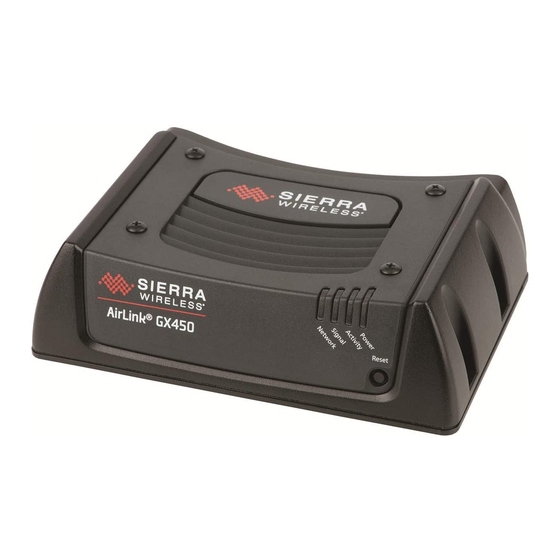
Sierra Wireless Airlink GX450 Quick Start Manual
Hide thumbs
Also See for Airlink GX450:
- Hardware user's manual (69 pages) ,
- Hardware user's manual (72 pages)
Advertisement
QUICK START GUIDE
GX450 Modem
This guide provides step-by-step instructions for a quick setup of the GX450 modem.
STEP 1: INSTALL THE SIM CARD
1. Ensure that the device is powered off.
2. Remove the four screws attaching the black cover to the gateway's body and then remove the cover.
3. Slide the SIM card into the SIM card holder. Note the location of the notched corner for correct alignment.
4. Re-attach the cover using all 4 screws to maintain the IP64 rating.
STEP 2: CONNECT THE CELLULAR ANTENNA
1. Attach the supplied antenna to the magnetic antenna base. Note the rubber O-ring location to ensure a proper seal.
2. Attach the magnetic antenna base cable to the GX450 cellular connector. The GPS and Diversity connectors will not be used.
TRANSFORMING THE WAY THE WORLD WORKS
Advertisement
Table of Contents

Subscribe to Our Youtube Channel
Summary of Contents for Sierra Wireless Airlink GX450
- Page 1 QUICK START GUIDE GX450 Modem This guide provides step-by-step instructions for a quick setup of the GX450 modem. STEP 1: INSTALL THE SIM CARD 1. Ensure that the device is powered off. 2. Remove the four screws attaching the black cover to the gateway’s body and then remove the cover. 3.
- Page 2 STEP 3 CONNECT THE DISPLAY OR RECEIVER See the wiring diagrams. In all instances, ensure that the equipment is powered off before connecting it to the modem. AG-372 receiver 1. Ensure the receiver is powered off. 2. Using cable P/N 109863, attach connector P1 to Port B on the AG-372 receiver. 3.
-
Page 3: Item Description
WIRING DIAGRAM: AG-372 RECEIVER ❼ ❻ ❶ ❺ ❹ ❶ ❸ ❷ Item Description Item Description AG-372 antenna Mounting plate 62034 Power cable assembly, GX-450 modem 109863 Cellular antenna (international) 110024 GX450 modem Whip antenna (USA and Canada 51227 only) Magnetic antenna base cable 109989... - Page 4 WIRING DIAGRAM: TM-200 MODULE (FOR USE WITH THE TMX-2050 / XCN-2050 DISPLAY) ❽ ❾ ❶ ❼ ❶ ❻ ❺ ❷ ❸ ❹ Item Description Item Description TM-200 Module Mounting plate 62034 TM-200 14-pin power, CAN, and I/O cable 92676 Cellular antenna (international) 110024 Power cable assembly, GX450 modem 109862...
- Page 5 WIRING DIAGRAM: TM-200 MODULE WITH EXP-100 PORT REPLICATOR ⓬ Note: If the EXP-100 port ⓭ replicator is required and is not already installed, order P/N 101990-01. If the EXP-100 port replicator is already ⓫ ❶ installed, but without the ❻ Ethernet adaptor, ❷...
- Page 6 WIRING DIAGRAM: FMX / FM-1000 INTEGRATED DISPLAY ❾ ❶ ❿ ❽ ❷ ❶ ❼ ❻ ❺ ❸ ❹ Item Description Item Description USB hub 83517 Magnetic antenna base cable 109989 FmX® / FM-100™ integrated display Mounting plate 62034 Power assembly, FmX/FM-1000 integrated 110832 Cellular antenna (international) 110024...
- Page 7 WIRING DIAGRAM: CFX-750 / FM-750 DISPLAY ❾ ❶ ❿ ❽ ❷ ❶ ❼ ❻ ❺ ❸ ❹ Item Description Item Description USB hub 83517 Magnetic antenna base cable 109989 CFX-750™ /FM-750™ display Mounting plate 62034 Power assembly, CFX-750 display 110832 Cellular antenna (international) 110024 Power cable assembly, GX450 modem...
-
Page 8: Step 4: Connect To The Network
STEP 4: CONNECT TO THE NETWORK The first time the gateway is powered on its home network, it automatically starts the activation/provisioning process and attempts to connect to the network. This process typically takes 5-10 minutes. A successful connection is indicated by a solid green network LED. STEP 5: CONFIGURE THE NETWORK For most cellular plans, the modem will automatically configure itself properly. -
Page 9: Led Behaviour
LED BEHAVIOUR Color / Pattern Description Power No power or input voltage ≥ 36 VDC or ≤ 9 VDC. Solid green Gateway is connected to nominal power and is operating normally. Flashing amber / green Gateway has a GPS fix. Solid amber Gateway is entering a low power mode or system low level boot. - Page 10 FIRMWARE VERSION MATRIX Product Update to the following software version FmX / FM-1000 integrated display Version 10.01 or later, released December 2016 CFX-750 / FM-750 display Version 7.71 or later, released October 2016 TMX-2050™ / XCN-2050™ display Version 4.31 or later, released December 2016 AG-372 antenna Version 6.20 or later, released April 2016 ©...


Need help?
Do you have a question about the Airlink GX450 and is the answer not in the manual?
Questions and answers