
Related Manuals for Moxa Technologies EDR-810 Series


Summary of Contents for Moxa Technologies EDR-810 Series
- Page 1 Moxa Industrial Secure Router Hardware Installation Guide EDR-810 Series Second Edition, May 2014 2014 Moxa Inc. All rights reserved. P/N: 1802008100011 www.ipc2u.ru www.moxa.pro...
-
Page 2: Package Checklist
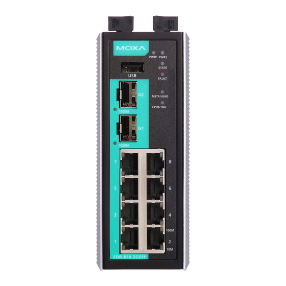
Package Checklist The Moxa Industrial Secure Router is shipped with the following items. If any of these items is missing or damaged, please contact your customer service representative for assistance. • 1 Industrial Secure Router • RJ45 to DB9 console port cable •... - Page 3 Panel Views of Industrial Secure Router Front Panel: 1. USB port for ABC-02 2. 1000Mbps SFP port 3. 1000Mbps SFP port speed LED indicator 4. Model name 5. Power input PWR1 LED indicator 6. Power input PWR2 LED indicator 7. STATE LED indicator 8.
-
Page 4: Mounting Dimensions (Unit = Mm)
Mounting Dimensions (unit = mm) DIN-Rail Mounting The aluminum DIN-Rail attachment plate should already be fixed to the back panel of the Industrial Secure Router when you take it out of the box. If you need to reattach the DIN-Rail attachment plate to the Industrial Secure Router, make sure the stiff metal spring is situated towards the top, as shown in the following figures. -
Page 5: Wiring Requirements
STEP 2—Mounting the EDR-810 on the wall requires four screws. Use the EDR-810, with wall mount plates attached, as a guide to mark the correct locations of the 4 screws. The heads of the screws should be less than 6.0 mm in diameter, and the shafts should be less than 3.5 mm in diameter, as shown in the figure on the right. - Page 6 ATTENTION Safety First! Be sure to disconnect the power cord before installing and/or wiring your Moxa Industrial Secure Router. Calculate the maximum possible current in each power wire and common wire. Observe all electrical codes dictating the maximum current allowable for each wire size. If the current goes above the maximum ratings, the wiring could overheat, causing serious damage to your equipment.
-
Page 7: Wiring The Relay Contact
Wiring the Relay Contact The Industrial Secure Router has one set of relay outputs. This relay contact uses one contacts of the terminal block on the Industrial Secure Router’s top panel. Refer to the next section for detailed instructions on how to connect the wires to the terminal block connector, and how to attach the terminal block connector to the terminal block receptor. -
Page 8: Wiring The Digital Inputs
Wiring the Digital Inputs The Industrial Secure Router has one set of digital input, DI. The DI consists of two contacts of the 2-pin terminal block connector on the Industrial Secure Router's top panel, which are used for the DC inputs. The top and front views of one of the terminal block connectors are shown here. -
Page 9: 10/100Baset(X) Ethernet Port Connection
RJ45 (10-pin) to DB9 (F) Cable Wiring 10/100BaseT(X) Ethernet Port Connection The 10/100BaseT(X) ports located on Moxa Industrial Secure Router’s front panel are used to connect to Ethernet-enabled devices. Most users will choose to configure these ports for Auto MDI/MDI-X mode, in which case the port’s pinouts are adjusted automatically depending on the type of Ethernet cable used (straight-through or cross-over), and the type of device (NIC-type or HUB/Switch-type) connected to the port. -
Page 10: The Reset Button
RJ45 (8-pin) to RJ45 (8-pin) Cross-Over Cable Wiring 1000BaseSFP Fiber Port The Gigabit Ethernet ports on the Industrial Secure Router are SFP slots, which require Gigabit mini-GBIC fiber transceivers to work properly. Moxa provides complete transceiver models for various distance requirements. The concept behind the LC port and cable is quite straightforward. -
Page 11: Led Indicators
LED Indicators The front panel of the Moxa Industrial Secure Router contains several LED indicators. The function of each LED is described in the following table: Color State Description Power is being supplied to power input P1 on the main module. PWR1 AMBER Power is not being supplied to power input... -
Page 12: Specifications
* STATE, FAULT, MSTR/HEAD, CPLR/TAIL LEDs blink in sequence when the system is importing/exporting files from ABC-02-USB. Specifications Technology Standards IEEE 802.3 for 10BaseT IEEE 802.3u for 100BaseT(X) IEEE 802.3z for 1000BaseX Protocols SNMPv1/v2c/v3, DHCP Server/Client, TFTP, NTP, HTTP, HTTPS, Telnet, SSH, Syslog, SMTP, LLDP, PPPoE, PPTP, Dynamic DNS, QoS Flow Control IEEE 802.3x flow control, back pressure flow... - Page 13 IEC 61000-4-2 (ESD), level 3; IEC 61000-4-3 (RS), level 3; IEC 61000-4-4 (EFT), level 3; IEC 61000-4-5 (Surge), level 3; IEC 61000-4-6 (CS), level 3 Shock IEC60068-2-27 Free Fall IEC60068-2-32 Vibration IEC60068-2-6 WARRANTY 5 years Technical Support Contact Information www.moxa.com/support Moxa Americas: Moxa China (Shanghai office): Toll-free: 1-888-669-2872...
Need help?
Do you have a question about the EDR-810 Series and is the answer not in the manual?
Questions and answers