
Related Manuals for Wecon LX3V-4DA


Summary of Contents for Wecon LX3V-4DA
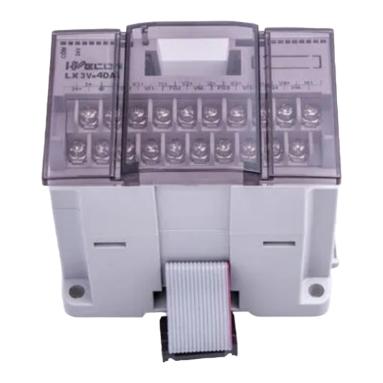
- Page 1 WECON LX3V-4DA Module Wecon Technology Co.,Ltd. Website: http://www.we-con.com.cn/en Technical Support: liux@we-con.com.cn Skype: “fcwkkj” or “Jason.chen842” Phone: 86-591-87868869 QQ Group: 465230233 Technical forum: http://wecon.freeforums.net...
- Page 2 DC (resolution: 5mV), or 0 to 20mA (resolution: 20µA) maybe selected independently for each channel. Data transfer between the LX3V-4DA and the LX3V main unit is by buffer memory exchange. There are 32 buffer memories (each of 16 bits) in the LX3V-4DA.
-
Page 3: Installation And Wiring
*3: If electrical noise or a voltage ripple exists at the output, connect a smoothing capacitor of 0.1 to 0.47uF, 25V. *4: Connect the terminal on the LX3V-4DA with the terminal on the MPU of the programmable controller. *5: Shorting the voltage output terminal or connecting the current output load to the voltage output terminal may damage the LX3V-4DA. - Page 4 4 digit hexadecimal number. The first digit will be the command for channel1 (CH1), and the second digit for channel 2 (CH2) etc. The numeric values of these four digits respectively represent the following items: WECON Technology Co., Ltd.
- Page 5 Offset/gain setting command: Changes offset and gain values of channels CH1 through CH4 by writing 1 to the corresponding Hex digits of BFM #8 or #9. The current values will be valid until this command is output. WECON Technology Co., Ltd.
- Page 6 The digital input or analog output The input or output value is in value is out of the specified range the specified range. Adjustment BFM #21 is not set to “1". Adjustable status prohibit status (BFM #21 = 1) WECON Technology Co., Ltd.
- Page 7 Note: BFM #’s marked E/ (E). Values of BFM #0, #5, and #21, (marked E) are stored in EEPROM memory of the LX3V-4DA. BFM #10 to #17 are copied to EEPROM when the gain/offset setting command BFM #8, #9 is used. Also, BFM #20 causes resetting of the EEPROM memory.
- Page 8 Data register D3→ BFM #4 (output to CH4) Operation procedure 1) Turn off the power of the MPU, and then connect the LX3V-4DA. After that, wire the I/O lines of the LX3V-4DA. 2) Set the MPU to STOP, and turn on the power. Write the above program then switch the MPU to RUN.
-
Page 9: Adjustment Of I/O Characteristics
LX3V-4DA module 6. Caution regarding operation 1) Check whether the output wiring and/or expansion cables are properly connected on LX3V-4DA analog special function block. 2) Check that the LX3V system configuration rules have not been broken, i.e. the number of blocks does not exceed 8 and the total system I/O is equal or less than 256 I/O.Ž... - Page 10 An example program for adjustment is shown below. The example shows that for channel CH2 of LX3V-4DA block No.1, the offset value is changed to 7 mA, and the gain value to 20 mA. Note that for CH1, CH3, and CH4.
-
Page 11: Troubleshooting
When X010 and X011 are off, transfer will not be executed, therefore the destination data value will not be changed. 9. Troubleshooting If the LX3V-4DA does not operate properly, check the following items: 1) Check the external wiring. Refer to section 3 of this manual. WECON Technology Co., Ltd. - Page 12 5) Check that the external load resistance connected to each analog output terminal does not exceed the capacity of the LX3V-4DA drive (voltage output: 2kΩ to 1 MΩ / current output: 500Ω).‘ 6) Check the output voltage or current value using a voltmeter or ammeter, and confirm that the output meets the I/O characteristics.
Need help?
Do you have a question about the LX3V-4DA and is the answer not in the manual?
Questions and answers