Advertisement
Quick Links
LX5V-2PTS-BD BD Module Manual
1 Installation
▪
Before installation, it must be ensured that the PLC host and the related device of the BD module terminal
wiring are powered off reliably. The shell is inserted into the BD module slot of PLC host, and then locked
with two standard screws for fixation.
▪
Two standard terminal heads are equipped with this BD module. After connecting the wiring, insert them
into its terminal. After confirming that the host, BD module, wiring, etc. are installed correctly, it can be
powered on for use.
▪
✎Note:
● Please install the BD module firmly and fix it on PLC. Poor contact may lead to failure.
● Tightening torque for fixing BD module or PLC top cover is 0.3N.m
avoid malfunction.
Warning: Cut off the power before installing, removing or wiring the BD module to avoid electric shock or
▪
product damage.
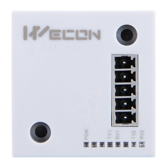
2 Appearance and terminal
Indicator
lamp
PWR
COM
CH1
CH2
Note:
The recommended range is -190℃ to 600℃), and the maximum display range is -200℃ to 610℃.
Table2 LED lamp function description
ON when power-on (when the program is running, it will be ON).
It flashes when communicating with PLC normally, and it is OFF when timeout.
Channel 1 lamp: Always on in range; Flashing outside the range of -190℃to600℃;
Off when the channel is closed.
Channel 2 lamp: Always on in range; Flashing outside the range of -190℃to600℃;
Off when the channel is closed.
0.6N.m. Please tighten it firmly to
to
Table1 Terminal distribution
2-wire/3-wire PT100 thermal resistance
Channel 2 sensor signal input V
V2+
positive
Channel 2 sensor signal input L
L2+
positive
VI-
Sensor common pole
Channel 1 sensor signal input L
L1+
positive
Channel 1 sensor signal input V
V1+
positive
Description
1
V1.0
Advertisement

Related Manuals for Wecon LX5V-2PTS-BD


Summary of Contents for Wecon LX5V-2PTS-BD
- Page 1 V1.0 LX5V-2PTS-BD BD Module Manual 1 Installation ▪ Before installation, it must be ensured that the PLC host and the related device of the BD module terminal wiring are powered off reliably. The shell is inserted into the BD module slot of PLC host, and then locked with two standard screws for fixation.
-
Page 2: Specification
3 Specification (1) General specification: Same as PLC main unit. (Please refer to the accompanying manual of the PLC main unit.) (2) Power supply specification: The power supply is provided internally by PLC. (3) Performance specifications: Project Description Power supply 24VDC±10%, 50mA;... - Page 3 4 Wiring Wiring instructions: (1) 2-wire PT100: When using channel 1, V1+ and L1+ are shorted with wires, and the two leads of the sensor are connected to L1+ and VI- respectively. Similarly, when using channel 2, V2+ and L2+ are shorted with wires, and the two leads of the sensor are connected to L2+ and VI- respectively.
-
Page 4: Parameter Configuration
PLC (slot number 1 or 2, the software will select slot 1 by default, and right-click to move down to slot ③ After adding the BD module to the slot, double-click or right-click to select configuration parameters to enter LX5V-2PTS-BD configuration parameters interface, as shown in the following figure. Configure related parameters on this interface. - Page 5 Note: This function is only supported in the following versions of host computer, slave computer and BD module:...
- Page 6 (1) Supported host computer versions: Wecon PLC Editor2 2.1.204 and above, as shown in the following figure: (2) Supported slave computer versions: 2.061 and above, as shown in the following figure: (3) Supported BD module version number: 1013 and above, as shown in the following figure:...
- Page 7 The parameter configuration interface is as follows: 1、Module setting: Set response time (The response time is the interval time between PLC acquisition of BD module data. Range: 0.1ms to 3276.7ms). 2、PTS configuration: Check enable channel to set whether to enable the current BD module channel. Sensor type: PT100 by default.
- Page 8 Channel value = actual temperature value × gain value + offset value When the channel value deviates from the actual temperature value, the channel can be calibrated by setting the gain offset, for example: ▪ The input temperature of control channel is 0℃, the value of acquisition channel is 30 (unit: 0.1℃), and the actual channel value should be 0 (unit: 0.1℃).
-
Page 9: Ladder Diagram
3、Set I/O mapping. The channels are mapped to R device according to the current number of BD module channels by default. As shown in the following figure, BD module CH1 to CH2 is mapped to device R0 to R1. 4、After the above configuration is completed, check the program, download the configuration to PLC, and STOP→RUN configuration takes effect. - Page 10 2.Programming example using "BD module configuration" function of host computer software: Map CH1 into R0 device Map CH2 into R1 device 6.3 BD monitoring interface and buffer memory Open the module monitoring interface, select BD module, select LX5V-2PTS from the list of BD modules on the right to monitor it online, and check the current BD module communication status and error information in time.
- Page 11 0: Channel closed; 1: Channel Channel 2 status 0x2182 × 0 to 2 opened information 2: Channel value exceeds the range 0: No error; 1: Channel value 0x2184 × Channel 2 error code 0 to 1 exceeds the range ② Universal buffer memory (BFM): Used to diagnose the communication status of the currently connected BD module.
Need help?
Do you have a question about the LX5V-2PTS-BD and is the answer not in the manual?
Questions and answers