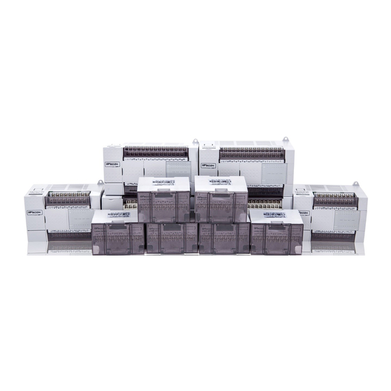
Summary of Contents for Wecon LX3V-8ITC
- Page 1 LX3V-8ITC User manual Website: http://www.we-con.com.cn/en Technical Support: support@we-con.com.cn Skype: fcwkkj Phone: 86-591-87868869 QQ: 1043098682 Technical forum: http://wecon.freeforums.net/...
-
Page 2: Brief Introduction
14-bit readable data to store in the main processing unit (MPU). The temperature is readable in degrees Celsius or Fahrenheit. All data transfer and parameter settings can be adjusted by WECON PLC Editor software; FROM / TO instruction can be used for reading and writing data. - Page 3 Type K: DX-G, KX-GS, KX-H, KX-HS, WX-G, EX-H, VX-G Type J: JX-G, JX-H Type S: SC-G, SC-H Type N: NC-G,NC-H Type E: EX-G, EX-H Type T: TX-G, TX-H Type B: BC-G, BC-H Type R: RC-G, RC-H WECON Technology Co., Ltd.
-
Page 4: Installation Instructions
If the AC power is connected to the DC I / O terminal or the DC power supply terminal, the PLC may be destroyed. 4) Do not connect external wiring to the terminals not used on LX3V-8iTC and PLC, for this connection may damage the device. - Page 5 Type R Type R below 800 C: 1.87 below 1472 C: 3.366 average accuracy The average accuracy for above 800 C: 1.32 above 1472 C: 2.376 Type S average accuracy of Type S The average accuracy of WECON Technology Co., Ltd.
-
Page 6: Buffer Memory
It has optical isolation between analog and digital circuits. DC/DC converter is applied Isolation to isolate between this device and MPU. It has signal isolation between each analog channel. 5. Buffer Memory 5.1 Allocation of Buffer Memory Latch Defaul Register W/R Contents CH1->CH4 CH5->CH8 WECON Technology Co., Ltd. - Page 7 Input data must be hexadecimal, only support to setting input 0 or 1. Other input value is invalid, and the value of BFM26 (BFM66) shows the allowed one by last input. Among which, 26 controls the first 4 channels, and WECON Technology Co., Ltd.
- Page 8 Communication board software version number number Version Acquisition board software version number number #33->#39 #73->#79 Reserve - Reserve Note: Symbol Description O represents maintainer line, X represents non-maintainer line, R represents readable data, W represents writable data. WECON Technology Co., Ltd.
- Page 9 BFM # 27 / BFM # 47 sets the thermocouple cold-end compensation mode. Each bit of the 4-bit hexadecimal number corresponds to one channel, BFM#27 sets 1 to 4 channels, and the last bit sets channel 1. BFM # 47 sets 5 to 8 channels, and the last bit sets channel 5. WECON Technology Co., Ltd.
- Page 10 Normal power hardware A / D converter or other Normal hardware error hardware failure b4 to b9: reserve Reserve Reserve b10: data range Data output / analog input Normal data output error value is out of specification WECON Technology Co., Ltd.
-
Page 11: System Block Diagram
Use FROM instruction to read the ID code or ID number of special function module from the buffer memory BFM # 30 or BFM # 70. The ID code of LX3V-8iTC unit is K2038. Use this ID code in the user program of programmable controller to confirm this special function module before transmitting / receiving data. - Page 12 4) This step provides optional monitoring of the error buffer memory (# 29) of the LX3V - 8iTC. If there is an error in LX3V-8iTC, b0 of BFM # 29 will be set to ON. This can be read out by this program step and output as a device in LX3V programmable controller (M3 in this case).
-
Page 13: Initial Check
8. Diagnosis 8.1 Initial Check 1) Check if the input / output wiring and / or extension cable are connected to the LX3V-8iTC analog special function module. 2) Check does not violate the system configuration rules of LX3V, for example: the number of special function modules cannot exceed 8, and the total number of system I / O points cannot exceed 256. -
Page 14: Error Check
Depending on the close extent to the main unit, each special module is numbered from 0 to 15. Up to 16 special modules can be connected. WECON Technology Co., Ltd. -
Page 15: Emc Measures
EMC measures should include the selection of high quality cables that are well wired to avoid potential sources of noise. In addition, signal averaging is recommended to reduce the "puncture" effect of random noise. Version: V1.0.0 Date: Aug 2018 WECON Technology Co., Ltd.


Need help?
Do you have a question about the LX3V-8ITC and is the answer not in the manual?
Questions and answers