Table of Contents
Advertisement
1 . 1 . 1 . 1 . General instructions:
Thank you for purchasing a MS5308 LCR digital bridge meter.
The MS5308 LCR digital bridge meter is a professional
instrument for measuring inductance, capacitance and resistance.
It has many features, such as automatic identification, automatic
measurement range, high measurement accuracy and speed, wide
measuring range and so on.
An ordinary multimeter only provides DC mode for resistance
measurement, while the MS5308 provides both AC and DC
measurement modes. A variety of test frequencies up to 100Khz
can be provided for inductance, capacitance and resistance in AC
mode to meet the actual needs better.
Correct usage can ensure that the instrument will work precisely
for a long time. Please read the instructions carefully before using
and operate the instrument strictly in accordance with the
instructions .
. . . .
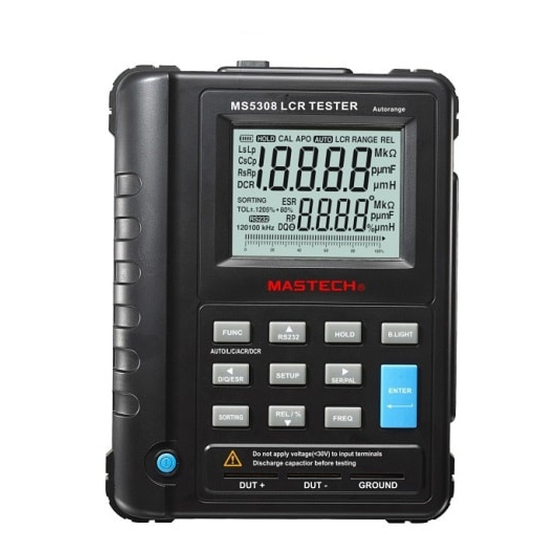
1.1
Panel description
1
Display
2
Functional buttons area
3
Power switch
IR Port
4
5
External power port
6
Calibration button port
7
DUT + jack
8
DUT - jack
9
Shielding grounding jack
. . . .
1.2
I nspection
When you get a new LCR meter, please check the instrument and
its accessories. If something is damaged or missed, please contact
the store you bought the instrument from for adjustment or
replacement.
1.3 Accessories
MS5308 LCR digital bridge meter
SMD test probe
Upper computer program CD
Kelvin test clip (one pair)
IR data line
External power supply
Page 1 of 17
Advertisement
Table of Contents

Related Manuals for Mastech MS5308


Summary of Contents for Mastech MS5308
- Page 1 1 . 1 . 1 . 1 . General instructions: Thank you for purchasing a MS5308 LCR digital bridge meter. The MS5308 LCR digital bridge meter is a professional instrument for measuring inductance, capacitance and resistance. It has many features, such as automatic identification, automatic measurement range, high measurement accuracy and speed, wide measuring range and so on.
- Page 2 MS5308 panel Page 2 of 17...
- Page 3 2. Safety instructions: Operating environment and condition: < Elevation 2 000 m Relative humidity (RH) ≦ 80%RH Operating temperature 0 – 40°C Note: DO NOT input voltage at the measurement port. When measuring capacitance, please discharge first then measure, otherwise, the meter will be damaged. Storage and maintenance: Do not use alcohol or other solvents to clean the meter.
- Page 4 means that that the measured object is capacitive. 3.2 Series-parallel connection mode description This meter has series and parallel measurement modes. When the capacitance value of the measured object is large or inductance value is small, use the series mode for more accurate results. When the capacitance value of the measured object is small or inductance value is large, use the parallel mode for more accurate results.
- Page 5 Table 1 Resistance measurement scope Measurem Measurement Measureme Resolutio Accuracy 100Hz/120 200.00 0.01 1.0%+5d 100Hz/120 2.0000K 0.3%+5d 100Hz/120 20.000K 0.3%+5d 100Hz/120 200.00K 0.01k 0.5%+5d 100Hz/120 2.0000M 0.1k 1.0%+5d 100Hz/120 20.000M 1.0%+5d 100Hz/120 200.00M 0.1M 2.0%+5d 1kHz 20.000 0.001 1.0%+5d 1kHz 200.00 0.01 0.3%+5d...
- Page 6 Table 2 Capacitance measurement scope Measurem Measurement Measure Resoluti Accuracy 100Hz/120 20.000nF 1.0%+5d 100Hz/120 200.00nF 0.01nF 0.5%+5d 100Hz/120 2000.0nF 0.1nF 0.5%+5d 100Hz/120 20.000uF 0.5%+5d 100Hz/120 200.00uF 0.01uF 1.0%+5d 100Hz/120 2000.0uF 0.1uF 2.0%+5d 100Hz/120 20.00mF 0.1mF 2.0%+5d 1kHz 2000.0pF 0.1pF 1.0%+5d 1kHz 20.000nF 1.0%+5d...
- Page 7 Table 3. Inductance measurement scope Measurem Measurement Measureme Resoluti Accuracy 100Hz/120 20.000mH 1.0%+5d 100Hz/120 200.00mH 0.01mH 0.5%+5d 100Hz/120 2000.0mH 0.1mH 0.5%+5d 100Hz/120 20.000H 0.5%+5d 100Hz/120 200.00H 0.01H 1.0%+5d 100Hz/120 2000.0H 0.1H 1.0%+5d 100Hz/120 20.000kH 2.0%+5d 1kHz 2000.0uH 0.1uH 1.0%+5d 1kHz 20.000mH 0.5%+5d 1kHz...
- Page 8 of a root of 1 + D 5. Meter probe measurement Use Kelvin clip or SMD clamp to connect according to the following diagram: Schematic diagram for using SMD clamp to measure Remarks: insert the plug correctly according to the diagram. Measurement can’t be done if inserted incorrectly Page 8 of 17...
- Page 9 Schematic diagram for using Kelvin clip to measure Remarks: insert the plug correctly according to the diagram. Measurement can’t be done if inserted incorrectly. Page 9 of 17...
- Page 10 6 Measurement operation description: 6.1. Automatic measurement: When the instrument is turned on, the instrument will enter automatic identification mode by default. At this time, insert the object to be measured to the measurement side. The instrument will automatically recognize that the object to be measured is capacitive resistance or inductor and display the measurement value in the main display, and display a corresponding D/Q/θ/value in the secondary display.
- Page 11 to select parameters, and the sample value and error will display on the LCD. You can modify sample value and error by operating direction arrows. Select the modification item by operating Ok button, and confirm the settings. Press Comparison button again to quit selection mode.
- Page 12 7.2 Backlight function: backlight will be enabled when you press Backlight button. Press Backlight button again to turn off the backlight. The backlight will turn off automatically after it is on for 60 seconds. 7.3 Battery power detection function: The meter has a battery power detection function.
- Page 13 Click NEXT to enter the next screen Page 13 of 17...
- Page 14 Click change to select the position to be changed Click OK to enter the next screen based on the diagram Click NEXT Page 14 of 17...
- Page 15 Click INSTALL and start installing Page 15 of 17...
- Page 16 Press Communication button. The RS232 symbol will show on the LCD display. At this time, you can send data via infrared port. Connect the infrared communication line between computer and MS5308. When the software is opened on the computer, the screen is shown as following Figure Ⅰ...
- Page 17 Screen Ⅰ Screen Ⅱ Page 17 of 17...
Need help?
Do you have a question about the MS5308 and is the answer not in the manual?
Questions and answers